
Circuit Diagram
Index 2084
SHANGHAI GM BUICK(Excelle)saloon car engine circuit diagram(four)
Published:2011/4/17 21:46:00 Author:muriel | Keyword: SHANGHAI GM BUICK(Excelle), saloon car, engine

Figure SHANGHAI GM BUICK(Excelle)saloon car engine circuit diagram(four) (View)
View full Circuit Diagram | Comments | Reading(319)
SHANGHAI GM BUICK(LaCROSSE) saloon car power seat circuit diagram(one)
Published:2011/4/17 21:42:00 Author:muriel | Keyword: SHANGHAI GM BUICK(LaCROSSE), saloon car , power seat

SHANGHAI GM BUICK(LaCROSSE) saloon car power seat circuit diagram(one) is as shown
(View)
View full Circuit Diagram | Comments | Reading(571)
SHANGHAI GM BUICK(LaCROSSE) saloon car anti-theft system circuit diagram(two)
Published:2011/4/17 21:39:00 Author:muriel | Keyword: SHANGHAI GM BUICK(LaCROSSE) , saloon car , anti-theft system

SHANGHAI GM BUICK(LaCROSSE) saloon car anti-theft system circuit diagram is as shown
(View)
View full Circuit Diagram | Comments | Reading(412)
SE9518 multi-pattern program control neon light with musics automatic control circuit
Published:2011/4/15 21:00:00 Author:Nicole | Keyword: program control, neon light, music, automatic control
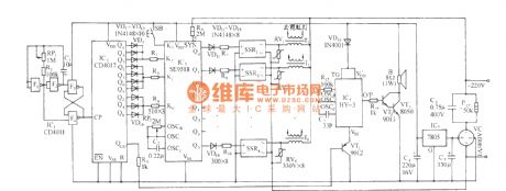
View full Circuit Diagram | Comments | Reading(404)
SH-123 flowing water horse-racing color lamp and "good luck" voice control circuit
Published:2011/4/15 20:54:00 Author:Nicole | Keyword: color lamp, voice control
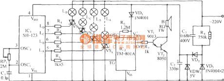
The control circuit is as shown. It consists of depressurization rectifier circuit, SH-123 four-way color lamp control circuit, good luck voice and power amplifier circuit. (View)
View full Circuit Diagram | Comments | Reading(533)
SH-802 many kinds of flashing patterns color lamps with disco music control circuit
Published:2011/4/15 20:46:00 Author:Nicole | Keyword: color lamp, disco music
View full Circuit Diagram | Comments | Reading(550)
SH-802 many kinds of flashing patterns color lamps with auspicious drum control circuit
Published:2011/4/15 20:44:00 Author:Nicole | Keyword: color lamp, drum control
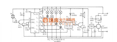
As shown in the figure, it is a mood changes control circuit with artificial touching. It consists of touching control circuit, color lamp control, vocal percussion, power amplifier circuit and AC depressurization rectifier circuit. SH-802 is color lamp control special integrated circuit. (View)
View full Circuit Diagram | Comments | Reading(789)
SHANGHAI GM BUICK(LaCROSSE) saloon car head-up display system circuit diagram
Published:2011/4/17 21:38:00 Author:muriel | Keyword: SHANGHAI GM BUICK(LaCROSSE), saloon car, head-up display system

SHANGHAI GM BUICK(LaCROSSE) saloon car head-up display system circuit diagram is as shown
(View)
View full Circuit Diagram | Comments | Reading(1293)
SHANGHAI GM BUICK(LaCROSSE) saloon car rearview mirror circuit diagram
Published:2011/4/17 21:37:00 Author:muriel | Keyword: SHANGHAI GM BUICK(LaCROSSE) , saloon car , rearview mirror

SHANGHAI GM BUICK(LaCROSSE) saloon car rearview mirror circuit diagram is as shown
(View)
View full Circuit Diagram | Comments | Reading(455)
SHANGHAI GM BUICK(LaCROSSE) saloon car power sunroof circuit diagram
Published:2011/4/17 21:36:00 Author:muriel | Keyword: SHANGHAI GM BUICK(LaCROSSE), saloon car , power sunroof

SHANGHAI GM BUICK(LaCROSSE) saloon car power sunroof circuit diagram is as shown
(View)
View full Circuit Diagram | Comments | Reading(1175)
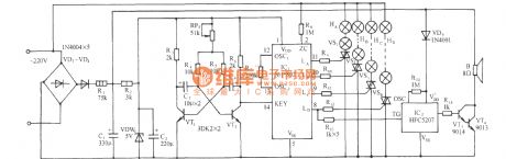
SH-803 festival color lamp with "good luck" voice control circuit
Published:2011/4/15 20:13:00 Author:Nicole | Keyword: festival color lamp, voice control
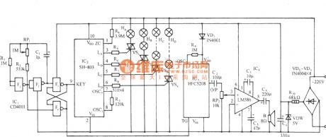
The circuit is as shown, adopting four-way color lamp eight kinds procedure mode to control the SH-803 color lamp control IC, and it uses HFC5208 language IC, whith the changing of color lamp, it sends out Wishing you prosperity, Fortune Blessing and festival greetings, to make the festive atmosphere thick. (View)
View full Circuit Diagram | Comments | Reading(1210)
SCR circuit using TCA780 and transistor amplification 59
Published:2011/4/17 21:08:00 Author:Nicole | Keyword: SCR, transistor
The SCR output current can reach 30A. Adopting potentiometer Rp1 can adjust output DC power. Because the integrated trigger TCA780 only has about 50mA output current, the SCR needs 1A control current, so it should connect a amplifier circuit composed of NPN tube. (View)
View full Circuit Diagram | Comments | Reading(734)
Delayed light out circuit of motorcycle brake light
Published:2011/3/31 2:26:00 Author:Nicole | Keyword: delayed light out, motorcycle brake light


The circuit principle as shown: S1 is power switch, controlled by frame lock, S2 is brake light control switch. closing switch S1, because the voltage in both ends of capacitor can be sudden changed, IC's ② pin is low level, brake light H on, a few seconds later, C1 is discharged, then the IC's ② pin voltage is higher than 1.6V, light H off. When the driving motorcycle is slow down or stop in an emergency, switch S2 is closed and shortened circuit both ends of C1 then discharge, turn switch IC's ② pin into low level, brake light H is lighted immediately, S2 resets, H is extinguished after a few seconds later.
IC in the circuit is high power switch integrated circuit TWH8752, the maximum current is 4A, H is rear brake light, R1 is 470K, C1 uses 16V, 47μF electrolytic capacitor, C2 uses 25V, 2200μF electrolytic capacitor, VD1 uses 1N5408 rectifier diode. If it needs to change the delay time, just to change the values of R1, C1 appropriately.
(View)
View full Circuit Diagram | Comments | Reading(626)
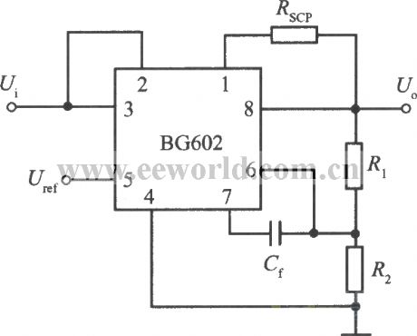
Standard application circuit of 8end adjustable output miniwatt integrated regulator BG602
Published:2011/3/21 20:21:00 Author:muriel | Keyword: 8end, adjustable , output , miniwatt , integrated , regulator, BG602
View full Circuit Diagram | Comments | Reading(435)
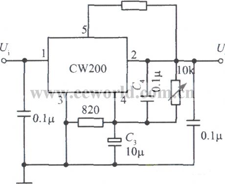
Low ripple integrated regulated voltage power supply with CW200
Published:2011/3/30 2:20:00 Author:muriel | Keyword: low ripple , integrated , regulated voltage power supply
View full Circuit Diagram | Comments | Reading(436)
General-purpose function generator
Published:2011/4/17 20:52:00 Author:Ecco | Keyword: general-purpose , function generator
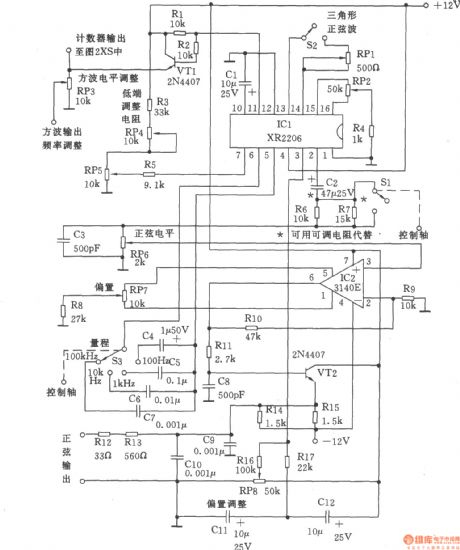
Signal generator can be divided into three parts: the sine wave and triangle wave generator, counter and pulse and ramp generator. The circuit is as shown, XR2206 adopts voltage controlled oscillator, the frequency adjustment is achieved by potentiometer RP5 (10k), it is easy to adjust to the frequency in one-thousandth. If you change the resistance of the fixed resistor R3, the resistance of the RP5 could also be changed. Sine and triangular waves is different from other similar instruments, the attenuator switch Sl only can change the magnitude of signal, it does not affect the bias voltage. According to the need, the fixed attenuation can be got (to 20dB, the voltage ratio is 10), it adjusted by R6, fixed resistor R7 connecting in parallel. It also could connect to rheostat to adjust resistance. Although the adjustment of resistance is more expensive, but it is easy to implement.
(View)
View full Circuit Diagram | Comments | Reading(3399)
A mobile phone charger circuit
Published:2011/4/17 20:19:00 Author:May | Keyword: mobile phone charger
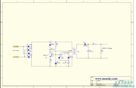
View full Circuit Diagram | Comments | Reading(4738)
NE555 alarm circuit diagram
Published:2011/4/17 20:36:00 Author:Ecco | Keyword: alarm circuit

The alarm is composed of two parts of the transmitting and receiving. Transmitting circuit is shown in Figure 1. It consists of two vibration temperature circuits with different frequencies and they are composed of two 555 time-base circuits. When the two ends of CK are in short circuit, the first(IC1) 555 constitutes a low-frequency shock temperature circuit, the frequency F1 is mainly decided by C1, R2, the output frequency of pin 3 is the low-frequency signal of F1. When the output of pin 3 is in high level, the second (IC2) 555 constitutes a high-frequency shock temperature circuit, the frequency F2 is mainly decided by C3, R4, and F2 much higher than F1, so the output of pin 3 is the pulse modulated signal of F2. The modulation signal throughs the driving circuit composing of Q1, T1, C5, C6 and produces high frequency modulation pulse on the power line, the voltage of high frequency modulation pulse is decided by transmission distance.
(View)
View full Circuit Diagram | Comments | Reading(1145)
74 series digital circuit of 7422 74H22 2 input/3 output and-nor gate
Published:2011/4/1 22:18:00 Author:Ecco | Keyword: digital circuit, 2 input , 3 output , and-nor gate
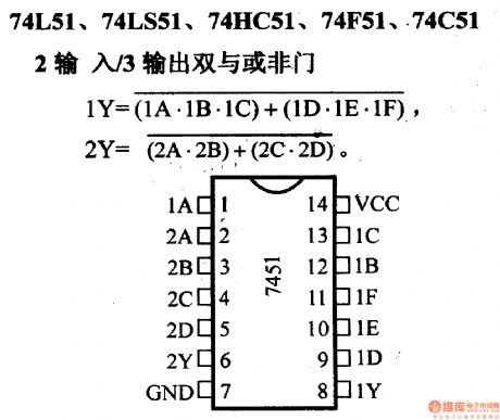
74 series digital circuit of 7422 74H22 2 input/3 output and-nor gate (View)
View full Circuit Diagram | Comments | Reading(521)
74 series digital circuit of 7497 synchronous 6 binary coefficient multiplier
Published:2011/4/2 3:58:00 Author:Ecco | Keyword: digital circuit , synchronous 6 , binary coefficient, multiplier

Executive fixed coefficient or variable coefficient fractional frequency: typical highest clock frequency 32MHz; When clearing, choose input for low level, counter begins the work, the output frequency equals to input frequency multiplied by input coefficient divided by 64.
H is high level, L is low level, X is uncertain, others are digital reading. 1. This is a simple chart to show the clearing function. The state of clock and strobe will make an influence on the logic level of Y and Z. For example, the unit /cascade is in low level, the output will keep high level. 2. The coefficient in input terminal is constant or variable coefficient input. 3. The unit/cascade is not allow to output Y. (View)
View full Circuit Diagram | Comments | Reading(632)
| Pages:2084/2234 At 2020812082208320842085208620872088208920902091209220932094209520962097209820992100Under 20 |
Circuit Categories
power supply circuit
Amplifier Circuit
Basic Circuit
LED and Light Circuit
Sensor Circuit
Signal Processing
Electrical Equipment Circuit
Control Circuit
Remote Control Circuit
A/D-D/A Converter Circuit
Audio Circuit
Measuring and Test Circuit
Communication Circuit
Computer-Related Circuit
555 Circuit
Automotive Circuit
Repairing Circuit