
Circuit Diagram
Index 2092
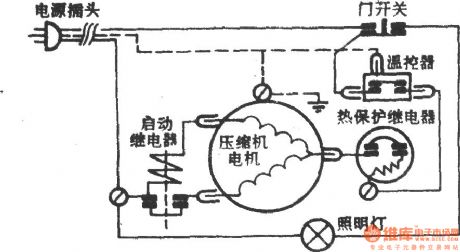
Aegean Islands - Bohai haier BCD-161 refrigerator
Published:2011/4/15 1:04:00 Author:Ecco | Keyword: Aegean Islands , Bohai haier , refrigerator

View full Circuit Diagram | Comments | Reading(611)
The arctic ocean - Ariston BYD-177 refrigerator
Published:2011/4/15 1:09:00 Author:Ecco | Keyword: The arctic ocean , Ariston , refrigerator
View full Circuit Diagram | Comments | Reading(481)
Sunflower BC-100 Refrigerator
Published:2011/4/15 1:06:00 Author:Ecco | Keyword: Sunflower , Refrigerator

View full Circuit Diagram | Comments | Reading(699)
Huayi - Ariston BCD-161,180,185 refrigerator
Published:2011/4/15 0:58:00 Author:Ecco | Keyword: Huayi , Ariston , refrigerator

View full Circuit Diagram | Comments | Reading(503)
Meilin - Ariston BCD-185E refrigerator
Published:2011/4/15 1:01:00 Author:Ecco | Keyword: Meilin, Ariston , refrigerator

View full Circuit Diagram | Comments | Reading(522)
Huayi - Ariston BCD-185 refrigerator
Published:2011/4/15 0:59:00 Author:Ecco | Keyword: Huayi , Ariston , refrigerator

View full Circuit Diagram | Comments | Reading(747)
Huayi - Ariston BCD-202 refrigerator
Published:2011/4/15 0:57:00 Author:Ecco | Keyword: Huayi , Ariston , refrigerator

View full Circuit Diagram | Comments | Reading(570)
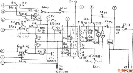
ZDD-12-160 Automatic multi-function inverter power supply
Published:2011/4/15 0:55:00 Author:Ecco | Keyword: Automatic, multi-function, inverter, power supply
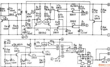
ZDD-12-160 Automatic multi-function inverter power supply preamp circuit:
ZDD-12-160 Automatic multi-function inverter power supply last stage amplifier circuit:
(View)
View full Circuit Diagram | Comments | Reading(1035)
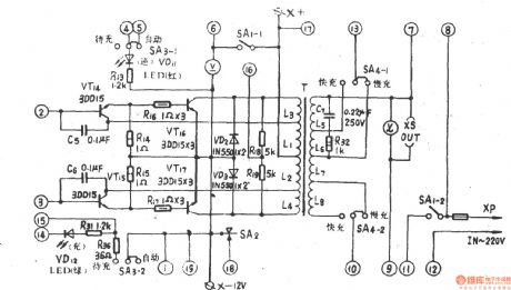
ZDD-I-160 Automatic multi-function inverter power supply
Published:2011/4/15 0:52:00 Author:Ecco | Keyword: Automatic, multi-function , inverter, power supply
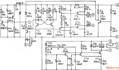
ZDD-I-160 Automatic multi-function inverter power supply preamp circuit:
ZDD-I-160 Automatic multi-function inverter power supply final stage circuit:
(View)
View full Circuit Diagram | Comments | Reading(1763)
The alarm circuit diagram of miner light
Published:2011/4/14 21:13:00 Author:Ecco | Keyword: alarm circuit , miner light

In the circuit, the batteries of miner's lamp is used as power supply and installed in the mine cap. When the gas is over the limit, the light bulb will automatically flash with the alarm. This circuit uses few components, it has no impact on the miner's work, it has the advantages of low cost, adjustable alarm points, easy to carry. (View)
View full Circuit Diagram | Comments | Reading(553)
The alarm circuit diagram for safety box and other metal objects
Published:2011/4/14 21:25:00 Author:Ecco | Keyword: alarm circuit , safety box , metal objects

When someone touches the safety box or other protected metal objects, in order to get the photo of the toucher, the sensor circuit inputs a pulse to the alarm circuit, and its positive edge will start the semiconductor and thyristor flash GE, then driving the camera work.
(View)
View full Circuit Diagram | Comments | Reading(1009)
Linear vco(8038、μA741)
Published:2011/4/14 22:46:00 Author:Ecco | Keyword: Linear , vco
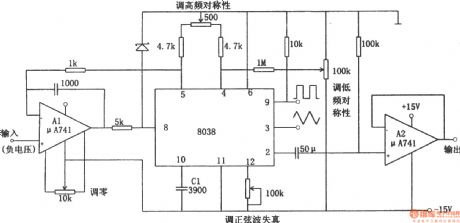
The linear voltage-controlled oscillator circuit is shown as the chart. In the figure, A1 is a constant current source circuit which is used to improve charging and discharging characteristics of C1. It makes a linear relationship between the output frequency and the input control voltage. A2 is a sine wave output buffer. If inputting the low-frequency sawtooth to the control voltage terminal, the circuit will become a linear sweep generator. But putting a signal voltage on input terminal will make the circuit output frequency modulation wave. The circuit can be used as an A / D converter changing a digital signal into the voltage with a frequency counter counting the output. Linear VCO is also known as V / F converter. (View)
View full Circuit Diagram | Comments | Reading(3773)
Rick McIntosh amplifier circuit
Published:2011/4/14 2:25:00 Author:Ecco | Keyword: Rick McIntosh

In the single-end push-pull circuit, for example, in Figure 23-8, a and C point are linked to be in low potential. But the earth point is not limited, any points on the coil a-b associating with the same potential point on the coil o-d can be used as earth point. In Figure 23-12, to connect the two mid-points of a-b, o-d to the earth, this is the basic form of Rick McIntosh amplifier circuit.
The two primary coils of the output transformer in circuit are directly related to the two primary coils of single-ended push-pull circuit, the everywhere's potential along the two potential coils is the same, so the primary coil is not influenced by electrostatic distributed capacitance, although they are two-lane around. This is one feature of Rick McIntosh amplifier circuit.
(View)
View full Circuit Diagram | Comments | Reading(412)
The basic form of two-stage amplifier voltage feedback circuit diagram
Published:2011/4/14 2:27:00 Author:Ecco | Keyword: basic form , voltage feedback , two-stage amplifier

The basic form of circuit diagram
Figure 19-1 shows the most representative form of two-stage negative feedback amplifier circuit. In this circuit, the feedback voltage of the R1 connects to the input signal in series, so the circuit is in series input type. In the figure, the plate load impedances of R1 and V1 are series connected, on the other hand, the plate load impedances of R1 and V1 are parallel connected to R2. So the circuit is a current feedback circuit for V1, and a voltage feedback circuit for V2. In fact, the current feedback component of V1 is much smaller than the total voltage feedback component of V2, so the whole circuit is used as a voltage feedback circuit.
(View)
View full Circuit Diagram | Comments | Reading(686)
The series input voltage feedback
Published:2011/4/14 2:28:00 Author:Ecco | Keyword: series input , voltage feedback

The figure 17-1 shows the basic form of the first-stage amplifier series input voltage feedback circuit.
(View)
View full Circuit Diagram | Comments | Reading(401)
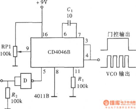
The quantitative pulse exported by CD4046
Published:2011/4/14 2:34:00 Author:Ecco | Keyword: quantitative pulse
View full Circuit Diagram | Comments | Reading(642)
Duplex output negative timing pulse circuit(555)
Published:2011/4/14 2:35:00 Author:Ecco | Keyword: Duplex output , negative, timing pulse , 555

View full Circuit Diagram | Comments | Reading(734)
Miaoshou AD-2100 therapeutic equipment circuit
Published:2011/4/14 3:10:00 Author:Ecco | Keyword: Miaoshou , therapeutic equipment

View full Circuit Diagram | Comments | Reading(661)
WB-74 Microwave electrizer circuit
Published:2011/4/14 3:10:00 Author:Ecco | Keyword: Microwave , electrizer circuit

View full Circuit Diagram | Comments | Reading(790)
Digital counter demonstration circuit
Published:2011/4/12 22:01:00 Author:Nicole | Keyword: digital counter

555 timer is used as clock to drive RS7490 decimal timer, BCD output to 7 section LED. To adjust R1 can change the clock frequency. (View)
View full Circuit Diagram | Comments | Reading(2621)
| Pages:2092/2234 At 2020812082208320842085208620872088208920902091209220932094209520962097209820992100Under 20 |
Circuit Categories
power supply circuit
Amplifier Circuit
Basic Circuit
LED and Light Circuit
Sensor Circuit
Signal Processing
Electrical Equipment Circuit
Control Circuit
Remote Control Circuit
A/D-D/A Converter Circuit
Audio Circuit
Measuring and Test Circuit
Communication Circuit
Computer-Related Circuit
555 Circuit
Automotive Circuit
Repairing Circuit