
Circuit Diagram
Index 2098
Suopu SP-220 induction cooker circuit
Published:2011/4/14 2:36:00 Author:Jessie | Keyword: induction cooker

View full Circuit Diagram | Comments | Reading(4515)
Supule SPL-10A induction cooker circuit
Published:2011/4/14 2:35:00 Author:Jessie | Keyword: induction cooker


View full Circuit Diagram | Comments | Reading(1353)
Orin induction cooker circuit
Published:2011/4/14 2:36:00 Author:Jessie | Keyword: induction cooker

View full Circuit Diagram | Comments | Reading(3978)
Haile DZC-1000W induction cooker circuit
Published:2011/4/14 2:16:00 Author:Jessie | Keyword: induction cooker

View full Circuit Diagram | Comments | Reading(2575)
Cadillac computer cable diagram
Published:2011/4/14 2:55:00 Author:Jessie | Keyword: computer cable

View full Circuit Diagram | Comments | Reading(518)
Lily DZC-1 induction cooker circuit
Published:2011/4/14 2:28:00 Author:Jessie | Keyword: induction cooker

View full Circuit Diagram | Comments | Reading(863)
Sanzhanjiao CFXB Insulation automatic electric rice cooker circuit diagram
Published:2011/4/14 3:00:00 Author:Jessie | Keyword: Insulation, automatic, electric rice cooker

View full Circuit Diagram | Comments | Reading(1714)
Sharp CY-103 induction cooker circuit
Published:2011/4/14 2:57:00 Author:Jessie | Keyword: induction cooker

View full Circuit Diagram | Comments | Reading(2101)
Ultrasonic humidifier overhaul circuit
Published:2011/4/14 2:56:00 Author:Jessie | Keyword: Ultrasonic humidifier, overhaul

View full Circuit Diagram | Comments | Reading(5089)
Massager circuit
Published:2011/4/14 3:04:00 Author:Jessie | Keyword: Massager


View full Circuit Diagram | Comments | Reading(788)
Linear DC voltage multiplier circuit
Published:2011/4/14 2:15:00 Author:Jessie | Keyword: Linear, DC voltage, multiplier

This circuit has two ICL8048 logarithmic amplifiers, ananti-logarithmic amplifier ICL8049, anda 741 op-amp. The relationship between output voltage andtwo input voltages is: Vo=V1V2/10. V1 and V2are +0.1 ~ +10VDC voltage. When the output voltageis +10V, its accuracyis 1%. (View)
View full Circuit Diagram | Comments | Reading(1154)
Operation amplifier phase buffer circuit
Published:2011/4/14 1:04:00 Author:Jessie | Keyword: Operation amplifier, phase buffer

In figure, thein-phase attenuator can be used as a voltage attenuation and a in-phase buffer. (View)
View full Circuit Diagram | Comments | Reading(542)
Operation amplifier adder circuit
Published:2011/4/13 22:52:00 Author:Jessie | Keyword: Operation amplifier, adder

In figure, thereis an inverse adder,it is a basic audio mixer. But this circuit is rarely used in real audio mixer. Because it can approximate op-amp's work limit, actually we recommend increasing the supply voltage to improve dynamic range. In-phase addercan be realized, but is not recommended. Because the impedance of signal source will affect circuit's gain. (View)
View full Circuit Diagram | Comments | Reading(847)
Photoelectric amplification circuit used in NC wire-cut machine
Published:2011/4/12 22:54:00 Author:Nicole | Keyword: NC wire-cut machine, photoelectric amplification

Photosensitive diode and BG1 form photoelectric conversion, BG2 and BG3 form Schmitt trigger, BG4 is inverter. When it is illumination, BG1 base potential rises, BG1 is off, then BG2 is conduction, BG2 is off, then BG4 is conduction, outputing positive singal. (View)
View full Circuit Diagram | Comments | Reading(509)
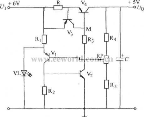
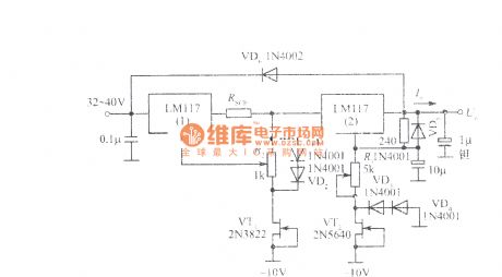
Steady voltage circuit only with 1V difference between input voltage and output voltage
Published:2011/4/13 2:21:00 Author:Nicole | Keyword: steady voltage, input voltage, output voltage
View full Circuit Diagram | Comments | Reading(494)
Thyristor circuit with 100W, 700W and 1000W output power
Published:2011/4/13 2:16:00 Author:Nicole | Keyword: Thyristor, output power

This is a non-contact power regulator circuit, the load is light La. To change 150kΩ potentiometer can achieve phase shift, and adding trigger voltage to bidirectional thyristor gate through bidirectional trigger, to control the conduction.
Main technical data: network voltage: 220±10%V; the adjustable range of output voltage: 10~230V; power: 100W, 700W, 1000W; bidirectional thyristor: TXC02-A60, TXC02-A6,; TXC03-A60; anti-interference capacitor: 0.22μF, 0.22μF, 0.27μF; the maximum environment temperature range: -15~+70℃, -15~+50℃, -15~+70℃.
The figures(b), (c) are the motor speed control practical circuit and illumination dimmer practical circuit, the maximum output power of later is 220W. (View)
View full Circuit Diagram | Comments | Reading(1274)
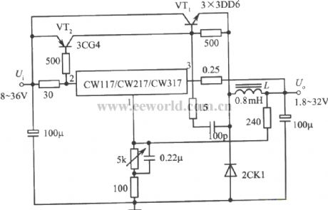
Switching integrated regulated power supply with 4A output current
Published:2011/4/13 2:24:00 Author:Nicole | Keyword: switching, regulated power supply, 4A output current
View full Circuit Diagram | Comments | Reading(507)
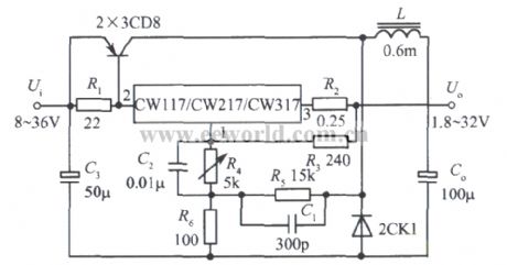
Switching integrated regulated power supply with 3A output current
Published:2011/4/13 2:27:00 Author:Nicole | Keyword: Switching, regulated power supply, 3A output current
View full Circuit Diagram | Comments | Reading(455)
RF driver audio oscillator
Published:2011/4/14 3:24:00 Author:Ecco | Keyword: RF driver, audio oscillator
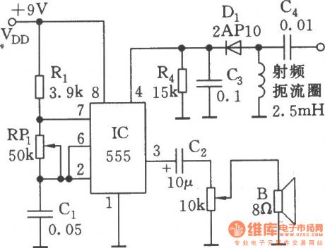
As shown, 555 and Rl, RPl, C1 and other components form controllable audio oscillator, f = 1.44 / (R1 +2 RP1) C1, the frequency of parameter in the diagram is between 600Hz ~ 20kHz, it can be adjustedby RP1.
(View)
View full Circuit Diagram | Comments | Reading(644)
Regulated power supply with adjustable output current and output voltage
Published:2011/4/13 2:30:00 Author:Nicole | Keyword: regulated power supply, output current, output voltage
View full Circuit Diagram | Comments | Reading(646)
| Pages:2098/2234 At 2020812082208320842085208620872088208920902091209220932094209520962097209820992100Under 20 |
Circuit Categories
power supply circuit
Amplifier Circuit
Basic Circuit
LED and Light Circuit
Sensor Circuit
Signal Processing
Electrical Equipment Circuit
Control Circuit
Remote Control Circuit
A/D-D/A Converter Circuit
Audio Circuit
Measuring and Test Circuit
Communication Circuit
Computer-Related Circuit
555 Circuit
Automotive Circuit
Repairing Circuit