
Index 141
ORYSTAL_OSCILLATOR_WITH_FM_CAPABILITY
Published:2009/6/23 1:51:00 Author:May

This crystal oscillator produces a good FM signal that can be tripled to 146 MHz and produces a clean 5-kHz deviation signal for FM voice. The bias control is adjusted for cleanest audio while the 1-to 5-pH cqil is adjusted to set the oscillator frequency to the exact setting required. (View)
View full Circuit Diagram | Comments | Reading(705)
RE_POWERED_SIDETONE_OSCILLATOR
Published:2009/6/23 1:50:00 Author:May
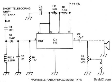
A sidetone oscillator is a special audio oscillator that is turned on and off with the transmitter. The oscillator is rf-driven and bat-tery operated. It uses a 555 IC timer as an astable multivibrator. Keying is accomplished by applying a positive dc potential, developed from the rf signal, to the reset terminal of the 555. (View)
View full Circuit Diagram | Comments | Reading(768)
STABILIZED_WIEN_BRIDGE_OSCILLATOR
Published:2009/6/23 1:50:00 Author:May

In this application, the AD534 is used as a vari-able-gain amplifier for the feedback signal from the output to the Y input, via the Wien bridge. The peak-rectifter and filter combination applies sufficient voltage to the X (denominator) input to maintain a stable oscillation-amplitude (with about 0.2% ripple). At startup, because X is small (divider mode), the gain is high, and the oscillation builds up rapidly. This is but one of several possible schemes, involving no extemal active elerrtents. Its forte is simplicity, rather than high performance; nevertheless, the amplitude is not greatly affected by supply and temperature variations, about 0.003 dB per volt, and 0.005 dB per degree. (View)
View full Circuit Diagram | Comments | Reading(0)
UJT_100_kHz_CALIBRATION_OSCILLATOR
Published:2009/6/23 1:49:00 Author:May

This unusual 100-kHz oscillator (whose fre-quency is determined by XTALl) can be used as a marker generator to calibrate the analog diai of a communication receiver, or its output can be fed to a divider courtter to produce a stable lower-fre-quency output for use as a clock-signal generator. (View)
View full Circuit Diagram | Comments | Reading(0)
CRYSTAL_OSCILLATOR_I
Published:2009/6/23 1:49:00 Author:May

In this circuit, series-resonant crystal XTAL1 is used as a frequency-determining element.XTAL1 is between 0.1 to 10 MHz. (View)
View full Circuit Diagram | Comments | Reading(0)
QUADRATURE_WAVE_OSCILLATOR
Published:2009/6/23 1:49:00 Author:May


By using a high-frequency quad current-feedback amplifier (the HA5025) as an RC oscillator, four quadrature sine waves can be generated. The HA5025's four separate amplifiers generate the sine waves, and the quad NAND gate, U2, is biased at its threshold, so it acts as a sine-wave to square-wave converter when the she waves are ac coupled into its input. (View)
View full Circuit Diagram | Comments | Reading(0)
FET_QUARTZ_CRYSTAL_OSCILLATOR
Published:2009/6/23 1:48:00 Author:May

This oscillator uses an MPF102 JFET as an active element. (View)
View full Circuit Diagram | Comments | Reading(0)
CODE_PRACTICE_OSCILLATOR_1
Published:2009/6/23 1:46:00 Author:May

Oscillator, works with 2 to 12 Vdc (but 9 to 12 volts gives best volume and clean keying). R1 can be replaced with a 500 K pot and the circuit wili sweep the entire audio frequency range. (View)
View full Circuit Diagram | Comments | Reading(0)
ASTABLE_OSCILLATOR_II
Published:2009/6/23 1:43:00 Author:May

By using transistor switch Q1/R2/R3, the frequency of an astable oscillator can be changed with a dc voltage or logic level. (View)
View full Circuit Diagram | Comments | Reading(0)
CODE_PRACTICE_OSCILLATOR
Published:2009/6/23 1:41:00 Author:May

This simple cpo uses the 7404 low-power Schottky hex inverter. C is a 5- to 30-μF electrolytic selected for the desired pitch. The speaker is a 2-inch, 8-ohm unit. (View)
View full Circuit Diagram | Comments | Reading(0)
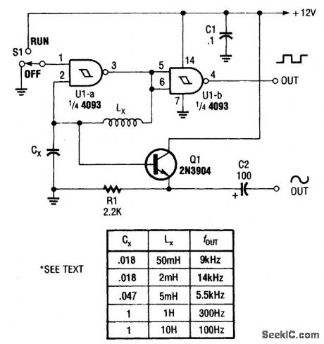
ASTABLE_OSCILLATORI
Published:2009/6/23 1:41:00 Author:May


In this circuit,two gates from the quad 4093 package are used to form a simple astable squarewave oscillator.The values for RX and CX are approximately as follows∶These values can be scaled for other frequencies. (View)
View full Circuit Diagram | Comments | Reading(0)
LOGIC_GATE_SINE_WAVE_OSCILLATOR
Published:2009/6/23 1:34:00 Author:May
An inductor and capacitor are used here as frequency-determining elements in an LC oscillator. (View)
View full Circuit Diagram | Comments | Reading(847)
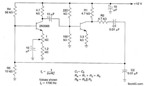
WIEN_BRIDGE_OSCILLATOR_II
Published:2009/6/23 1:33:00 Author:May

The operating frequency of this Wien-bridge oscillator is determined by C1, C2, R1, and R2. It can easily be modified to act as a tunable oscillator by substituting a dual-gang linear potentiometer for R1 and R2. (View)
View full Circuit Diagram | Comments | Reading(556)
WIEN_BRIDGE_OSCILLATOR_I
Published:2009/6/23 1:32:00 Author:May
View full Circuit Diagram | Comments | Reading(644)
CODE_PRACTICE_OSCILLATOR_PRODUCES_AUTOMATIC_DITS_AND_DAH
Published:2009/6/23 1:31:00 Author:May
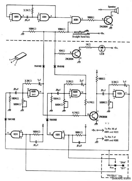
The circuit consists of a basic oscillator (above dashed line) and an automatic keyer (below dashed line). The unit can be used with a straight hand key or a paddle key for automatic operation. (View)
View full Circuit Diagram | Comments | Reading(608)
SIMPLE_VARIABLE_FREQUENCY_OSCILLATOR
Published:2009/6/22 23:55:00 Author:May
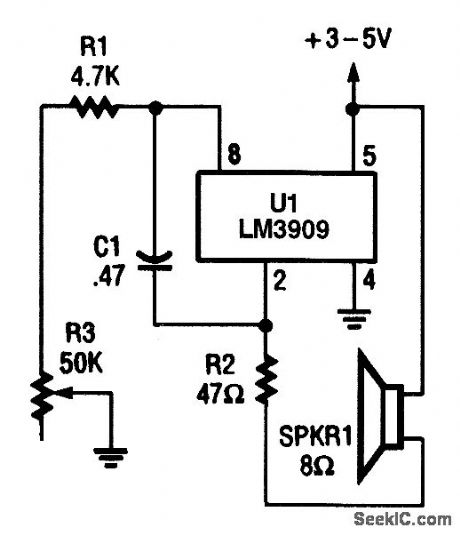


In this variable audio frequency oscillator, the output of U1 at pin 2 is used to drive an 8-Ω speaker through R2 (which functions as a current-limiter). (View)
View full Circuit Diagram | Comments | Reading(758)
VARIABLE_DUTY_CYCLE_FROM_ASTABLE
Published:2009/6/22 23:54:00 Author:May
If R1=R2=R3 and C1=C2=C3If potentiometer R3 is set at N%of rotation,thenTTOTAL≈0.7[(R+NR3)C+[R+[1-N)R3C]TTOTAL≈1.4 (R+R3)C and the duty Cycle can be varied without changing frequency. (View)
View full Circuit Diagram | Comments | Reading(797)
Audio oscillator with adjustable frequency composed of μA741
Published:2011/7/28 2:22:00 Author:Ecco | Keyword: Audio oscillator , adjustable frequency
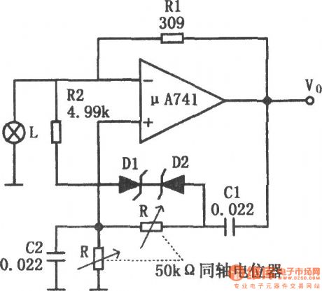
The chart shows the audio oscillator circuit with adjustable frequency. The circuit uses the lamp control circuit gain, but also increases the automatic gain control circuit composed of zener diode D1, D2 and resistor R2. As the frequency dropping, the output amplitude will increase. When the output amplitude increases to a predetermined value, zener diode is conducted, therefore, the amplifier gain reduces, so that it can avoid amplifier saturation. R2 is used to reduce the limiting effect of zener diode to avoid excessive distortion. Increasing R2, D1, D2 can make the adjusting range of oscillation frequency change from the 3:1 to 10:1. Using the components in figure, the oscillation frequency range is 200Hz ~ 2kHz. If R1, C1, C2 select the components with low temperature coefficient, then the temperature changes in the range of -55 ℃ ~ +125 ℃ , frequency stability is ± l%.
(View)
View full Circuit Diagram | Comments | Reading(632)
180~224kHz Carrier frequency generator
Published:2011/7/28 3:21:00 Author:Ecco | Keyword: 180~224kHz , Carrier frequency , generator
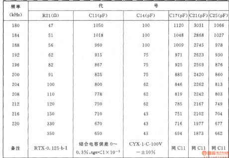
The generator shown in the chartcan be used in the channel modulation of carrier, the channel carrier frequency has 12 kinds:180kHz、184kHz、188kHz、192kHz、 196kHz、200kHz、204kHz、208kHz、212kHz、216kHz、220kHz、224kHz.
Component selection: Resistors: Rl、R48:3.9k、R2、R3、R8、R25、R32、R47:10k,R4、R9、R49、R52:3.3k,R5、R36:2k,R6、Rl9、R33、R41:20k,R7:24k,Rl0:110Ω,Rll:4.7k,Rl2:750Ω,Rl3、R23、R31、R50:1.3k,R14:560Ω,Rl5、Rl7、Rl8、R37、R38:510k,Rl6:910Ω,R20:16Ω,R21(See the table below),R22、R30:lk,R24、R29:300Ω,R26、R34、R43:2.7k,R27:180Ω,R28:1.5k,R35:240Ω,R39:300k,R40:1M,R42、R46:9.1k,R44:4.3k,R45:5.1k,R51:100k. The model is RTX-0.125W.
Potentiometer RPl: 4.7k,RP2:150Ω,RP3:680Ω,RP4:2.2kΩ.
Capacitor Cl C3,C7, Cl5, Cl6、C26~C29:0.047pF,C2, Cl9, C30:0.1μF,C4:510pF, C5, C8, C9, C20, C21~C24:5μF30V,C6:2400pF, Cl0(optical using when measurement ), Cll, Cl4, Cl7, C21, C25, see the table below, Cl2:20pF, Cl3:680pF, Cl7:5500pF, Cl8, C31, C32:50μF30V, C33, C34:0.22μF.
Diode: VD1, VD2, VD5, VD7~VDll, VDl4, VDl5:2CKl8 or 2CK72C, VDl2, VDl3, VDl7, VD20:2CPl4.
Regulator VD3, VDl6: 2CW5 (Current is6mA, regulator voltage is 12.5 ± 0.5V), VD4: 2CWl4 (voltage is 6.8 ± 0.2V), VDl9: 2DW7C. Varactor VD6i 2CC5.
LED VDl8: BT-201. Transistor VTl, VT4 ~ VT6, VT8 ~ VTl0: 3DG6C, β = 85 ~ 115, VT2: 3AG43, β = 50 ~ 85, VT3: 3DK28, β = 65 ~ 115, VT6, VTll: 3DGl28, β = 65 ~ 115 .
Relay K:] RW-3M. Inductance L: LH2A-straight-220μH (Inductors). Pulse transformer Tl: Model MX0-200, Ll-3, wound 12 turns, L2-3, L4-5, L6-7, L8-9are around with 24 turns, they are made of high strength magnet wire with Φ0.21mm.
(View)
View full Circuit Diagram | Comments | Reading(924)
TTL_BASED_AUDIO_OSCILLATOR
Published:2009/6/22 23:49:00 Author:May

Half a 7404 will produce a tone around 1000 Hz with this circuit. (View)
View full Circuit Diagram | Comments | Reading(0)
| Pages:141/195 At 20141142143144145146147148149150151152153154155156157158159160Under 20 |
Circuit Categories
power supply circuit
Amplifier Circuit
Basic Circuit
LED and Light Circuit
Sensor Circuit
Signal Processing
Electrical Equipment Circuit
Control Circuit
Remote Control Circuit
A/D-D/A Converter Circuit
Audio Circuit
Measuring and Test Circuit
Communication Circuit
Computer-Related Circuit
555 Circuit
Automotive Circuit
Repairing Circuit