
Index 146
FAST_LOGARITHM_GENERATOR
Published:2009/6/17 2:37:00 Author:May

In this circuit, EOUT=(constant)×logEIN. The circuit should be useable with op amps other than the ones illustrated. (View)
View full Circuit Diagram | Comments | Reading(591)
FUNCTION_GENERATOR_2
Published:2009/6/17 2:32:00 Author:May

A quad op amp makes up the heart of this function generator. U1-a generates a square wave, and outputs this to J3. J1 and J2 are pulse outputs obtained by differentiating the square wave. Integrator U1-b generates a triangle-wave shaper to obtain a sine wave. Q1 is an output amplifier. (View)
View full Circuit Diagram | Comments | Reading(2287)
100_dB_DYNAMIC_RANGE_LOG_GENERATOR
Published:2009/6/17 2:07:00 Author:May

EOUT=constane×(LogEIN). This circuit has 100-dB dynamic range, which is five decades of voltage change at the input. (View)
View full Circuit Diagram | Comments | Reading(574)
FUNCTION_GENERATOR
Published:2009/6/17 2:02:00 Author:May


This function generator,based on an LT1016 high-speed comparator,will generate from a single +5V supply. The slow rate of the op amps used determines the maxlmum useable frequency of this circuit. (View)
View full Circuit Diagram | Comments | Reading(11)
VISIBLE_LIGHT_AUDIO_TRANSMITTER
Published:2009/6/17 1:42:00 Author:May

In the visible-light transmitter, a 7805 volt-age regulator is connected in a variable-voltage configuration, and an audio signal is fed to the common input, to modulate the output voltage.The modulated output voltage is used to transmit intelligence via an incandescent larnp.
(View)
View full Circuit Diagram | Comments | Reading(1113)
LIGHT_WAVE_VOICE_COMMUNICATION_TRANSMITTER
Published:2009/6/16 23:54:00 Author:May


This transmitter uses a 741 op amp as a high-gain audio amplifier, which is driven by a rnicro-phone. The output of the 741 is coupled to Q1, which serves as the driver for a LED. Potentiometer RI is the amplifier's gain control. Miniature trimmer resistor R6 permits adjustment of the base bias of Ql for best transmitter performance. Gain control RI can be eliminated if C1 and R2 are con-nected directly to pin 2 of the 741. For maximum sensitivity, increase the value of R2 from 1 to 10MΩ and use a crystal microphone with a large diaphragm. (View)
View full Circuit Diagram | Comments | Reading(999)
FM_LIGHT_BEAM_TRANSMITTER
Published:2009/6/16 23:52:00 Author:May

This transmitter uses two-stage amplifier Q1/Q2 to frequency modulate an NE555 (configured as a VCO) operating at about 50 kHz. The resultant FM-modulated pulse train is converted to light pulses via LED1 through LED4, driven by Q3 and Q4. (View)
View full Circuit Diagram | Comments | Reading(507)
MODULATED_LIGHT_TRANSMITTER
Published:2009/6/16 23:48:00 Author:May

A light-bulb filament can be modulated with audio as a method of optical transmission. Ampli-fier Q1/Q2/Q3 drives emitter-follower TR4. Adjust R10 for the Q point (light bulb) giving best results.It should have a filament with low thermal inertia for best audio responses. (View)
View full Circuit Diagram | Comments | Reading(613)
NEGATIVE_ION_GENERATOR
Published:2009/6/16 23:31:00 Author:May

This oscillator-driver induces a high voltage in the windings of T2. (View)
View full Circuit Diagram | Comments | Reading(2930)
UNUSUAL_HALL_EFFECT_OSCILLATORS
Published:2009/6/16 22:01:00 Author:May

Although not intended for this application, Hall-effect switch can be used as the basis for a rather unusual oscillator. The oscillator can be reconfigured, as shown in Fig. B, to allow the circuit's oscillating frequency to be controlled via an RC network, comprised of RI and C1. (View)
View full Circuit Diagram | Comments | Reading(1502)
SMART_TURN_SIGNAL
Published:2009/6/16 1:59:00 Author:May

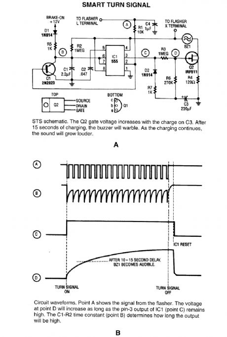


This circuit reminds a driver that his tun signal has been left on for more than 15 seconds. When stopped for a light, the brake-on signal holds the warning off. (View)
View full Circuit Diagram | Comments | Reading(690)
CRYSTAL_CONTROLLED_HARTLEY_OSCILLATOR
Published:2009/6/15 21:23:00 Author:May

View full Circuit Diagram | Comments | Reading(635)
PIERCE_OSCILLATOR
Published:2009/6/15 21:22:00 Author:May
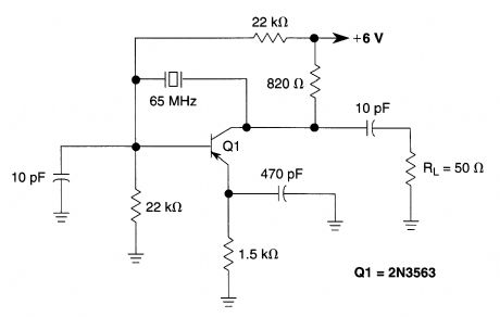
This Pierce oscillator uses a fundamental-mode 65-MHz crystal. (View)
View full Circuit Diagram | Comments | Reading(334)
WIDE_RANGE_CRΥSTAL_OSCILLATOR
Published:2009/6/15 21:21:00 Author:May
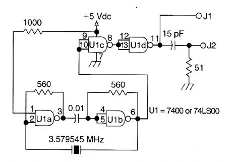
A circuit using one 7400 TTL IC can use crystals of the fundamental type, from 1 to about 13 MHz. Output is rich in harmonics, making this os-cillator useful for calibrations and test applica-tions. (View)
View full Circuit Diagram | Comments | Reading(556)
HEX_BUFFER_CRYSTAL_OSCILLATOR
Published:2009/6/15 21:09:00 Author:May

A 4049 single section acts as a crystal oscilla-tor, driving another section as a buffer, leaving four sections for other use. Use a 32- or 20-pF parallel resonant fundamental crystal. (View)
View full Circuit Diagram | Comments | Reading(665)
CRYSTAL_OSCILLATOR
Published:2009/6/15 21:04:00 Author:May
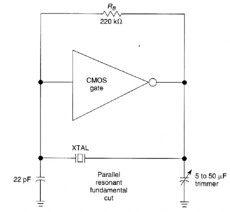
The CMOS amplifier is biased into the linear region by resistor RB. The pi-type crystal network (C1 and C2, and XTAL) provides the 180' phase shift at the resonant frequency which causes the circuit to oscillate. (View)
View full Circuit Diagram | Comments | Reading(1)
The liquid flowmeter
Published:2011/7/21 20:53:00 Author:qqtang | Keyword: liquid flowmeter
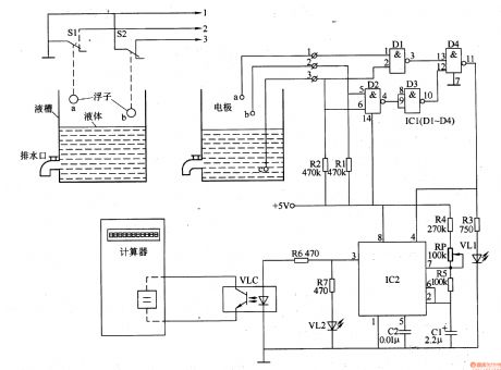
In industrial manufacturing, some situations need to measure the liquid flow and the rate. Here is to introduce the flowmeter which accumulates the liquid flowing time with ordinary octal bit computer, and then tests the distance between the poles according to the coverage of the liquid tank and the liquid level (set as 10cm), by which it computes the flow rate and volume of the liquid.The working principleThe liquid flowmeter consists of the liquid level detection control circuit, pulse generator and display circuit, see as figure 8-156.
(View)
View full Circuit Diagram | Comments | Reading(429)
The temperature central controller
Published:2011/7/22 20:53:00 Author:qqtang | Keyword: central controller
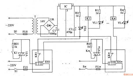
In industrial manufacturing and scientific researches, an electric heating box is always coupled with a temperature controller, this often happens in the spots where there are many electric heating boxes. Here is to introduce the temperature central controller which can constantly control the temperature of many electric heating boxes(or electric oven and electric cooker).The working principle of the circuitThe temperature central controller consists of the power supply circuit and the constant temperature control circuit, see as figure 8-127.
(View)
View full Circuit Diagram | Comments | Reading(434)
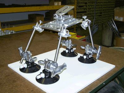
Supply Camera Car Sucker
Published:2011/7/19 7:16:00 Author:Sue | Keyword: Camera Car Sucker, Camera Sucker Eauipment, Supporting Bar, Vehicle Photography

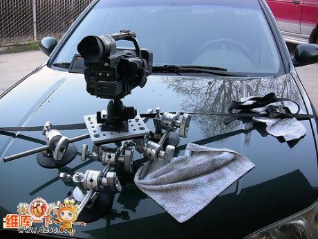
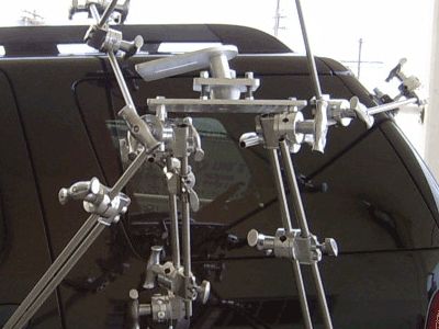
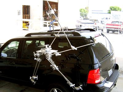
Camera Car Sucker.
Camera car suckers can be divided into three suckers, four suckers and multi-suckers. Any combination can be made according to cameras of different sizes.
It is suitable for automobile photography, moving photography, advertising photography, special effect photography. It is widely used in film and television play.
Four Suckers Equipment.
Multi-sucker Equipment.
Camera car sucker equipment includes:
Sucker, camera installation platform, universal joint, standing bar, rod, strap and carrying case.
(View)
View full Circuit Diagram | Comments | Reading(582)
Professional Secret Investigation Equipment
Published:2011/7/19 6:26:00 Author:Sue | Keyword: Secret Investigation, Candid


Features and Functions:
The microwave transmitter unit uses standard definition colorful SONY CCD digital camera and high sensitivity microphone. It has functions as simultaneous recording, transmission of audio and video signals.
It has internal 500mW transmitter and can use hard disk recording equipment. The micro-element code control circuit developed by our company and Japanese SONY, French DVR will realise remote control of the records.
The package transmitter uses DC10.8V, 1.5AH lithium battery as power supply and has a power supply time not shorter than 3 hours.
It uses imported components and modules which is of high quality with high cost performance. (View)
View full Circuit Diagram | Comments | Reading(451)
| Pages:146/195 At 20141142143144145146147148149150151152153154155156157158159160Under 20 |
Circuit Categories
power supply circuit
Amplifier Circuit
Basic Circuit
LED and Light Circuit
Sensor Circuit
Signal Processing
Electrical Equipment Circuit
Control Circuit
Remote Control Circuit
A/D-D/A Converter Circuit
Audio Circuit
Measuring and Test Circuit
Communication Circuit
Computer-Related Circuit
555 Circuit
Automotive Circuit
Repairing Circuit