
Index 159
The 4-time frequency circuit composed of CH7555
Published:2011/6/17 7:35:00 Author:Borg | Keyword: frequency circuit
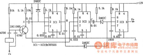
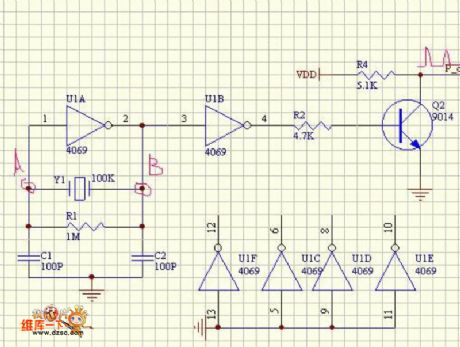
In the figure is the 4-time frequency circuit. This circuit consists of 3 CH7555 timers. When the symmetric wave is input, it is turned into the twice frequency by the phase inverter and the transistor. The two signals trigger the CH7555 single circuit at the same time, so that there generates two teams of pulses with different band widths on the output terminals of IC1 and IC2, then their dropping edges are to trigger the single stable circuit consisting of IC3, finally, a four-time frequency is generated on the output terminal of IC3. (View)
View full Circuit Diagram | Comments | Reading(424)
The frequency splitter composed of TTL decimal counter
Published:2011/6/22 2:21:00 Author:Borg | Keyword: frequency splitter, TTL decimal counter
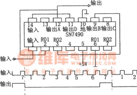
In the figure is the frequency splitter composed of TTL decimal counter. In many conditions, we need to do N spitting to the pulse sequence(N is an integral). For example, the digital clock needs 60 frequency splitting, so we get the pulses of 1Hz repeated frequencies; and also, the time standard generator needs to split the crystal oscillator output frequency. If the splitting parameter N≤10, then we only need a TTL binary-decimal counter SN7490. Usually, the frequency splitter of TTL circuits is a binary counter, which make every N input pulses launch a pulse. (View)
View full Circuit Diagram | Comments | Reading(621)
The frequency divider composed of R-S triggers (SN7442)
Published:2011/6/26 20:45:00 Author:Borg | Keyword: frequency divider, R-S triggers
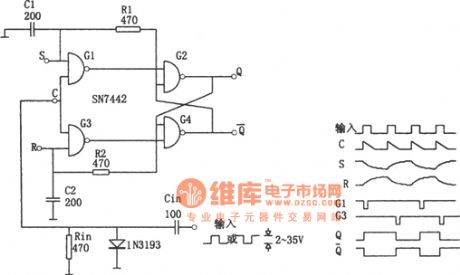
In the figure is the frequency divider composed of R-S triggers. The circuit can work in a wide frequency range and input pulse width. Compared with the standard R-S multi-resonance oscillator, the circuit must be stable after being improved. The integrator R1C1 and R2C2 form a feedback net, the integrating constant is selected according to the following formula: T<0.6RC, of which T is the width of the input pulse width. According to the above requirement, the NANDs of G1 and G2 won't output low LEVs at the same time. The working frequency of the circuit could be several MHz. (View)
View full Circuit Diagram | Comments | Reading(947)
The simple TV signal generator
Published:2011/6/17 22:35:00 Author:Borg | Keyword: signal generator
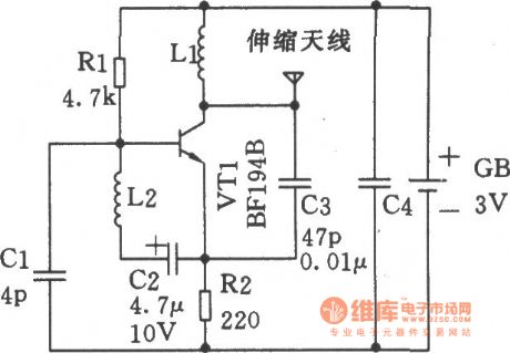
This generator can test if the TV receptor is good in 5 meters. See as the figure, the circuit is mainly a VFH oscillator, which consists of the triode BFI948 and the external components. The circuit can generate black-white stripe images on the TV screen and output an audio signal in the loudspeaker. The circuit only needs a 3V battery. In the circuit, both L1 and L2 use No.21 SWG high-intensity enameled wires to wind 8 turns around the hollow frame whose diameter is 5mm, by changing the value of the 4.7μF capacitor and the turns of L1 and L2, the number of the stripes and the sound frequency can be changed. (View)
View full Circuit Diagram | Comments | Reading(1142)
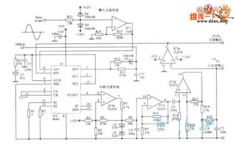
The NTSC system signal generator
Published:2011/6/22 2:09:00 Author:Borg | Keyword: NTSC, signal generator
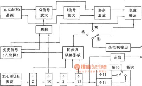
NTSC system signal generator is used in detecting and repairing multi-system color TV, satellite TV receiver, disc player, recorder, transistor and CD-G. The text is to introduce a practical, new, simple and cheap N system signal generator, whose field frequencies of 50Hz and 60Hz are changeable, apart from N system color stripes, octal stepped grey and grid, it can also generate a 50 travelling and 625 field checker grid. As the travel and field reference frequency is got by digital circuit frequency splitting, so the signal is stable and reliable, which can be the qualitative analysis detector.
(View)
View full Circuit Diagram | Comments | Reading(637)
The precise nA stage current generator
Published:2011/6/26 20:55:00 Author:Borg | Keyword: precise, nA stage, current generator
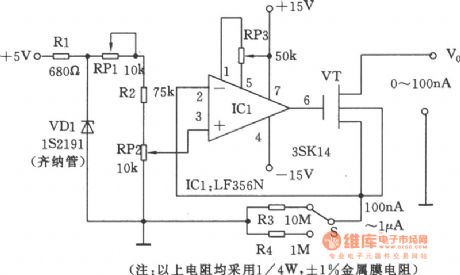
In real application, some special test circuits need the nA stage precise current as the reference, which is hard to make in the non-professional condition. In the figure is the precise nA stage current generator. This circuit is a constant micro current source. To make the current to be changed continuously and casually, as it is fixed with the multi-turn(10 turns) potentiometer as the divider to divide the reference voltage, so the value can be read out directly. Then by the current gear changing resistors of R3 and R4, the micro current of wide range is generated. (View)
View full Circuit Diagram | Comments | Reading(1389)
Simple seconds pulse generator (CD4017)
Published:2011/6/20 8:29:00 Author:Lucas | Keyword: Simple , seconds, pulse generator

View full Circuit Diagram | Comments | Reading(2333)
The ultra-high frequency emitting module CS901 circuit composed of SAW
Published:2011/6/26 21:20:00 Author:Borg | Keyword: ultra-high frequency, emitting module
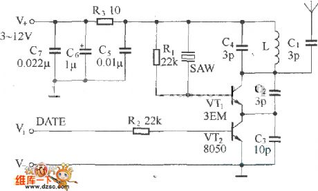
Figure:The ultra-high frequency emitting module CS901 circuit composed of SAW In the figure is the ultra-high frequency emitting module CS901 circuit composed of SAW, the model of the circuit is CS901, which adds the modulator VT2 and the power supply filter circuit on the base of basic circuits. The capacitors C5~C7 and R3 compose the power supply filter circuit, which avoid the disturbance of the power supply and improve the stability of the circuit. VT2 and R2 compose the modulation circuit, which is fixed at the emitting pole of the oscillating emitter VT1, the data signal is input from V1, by the control on VT2, the digital modulation of the emitting signal is completed. (View)
View full Circuit Diagram | Comments | Reading(711)
The simple square wave oscillator circuit
Published:2011/6/25 5:31:00 Author:Borg | Keyword: square wave, oscillator
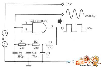
The simple square wave oscillator circuit is shown in the figure.
(View)
View full Circuit Diagram | Comments | Reading(732)
The basic wireless emitter circuit composed of SAW oscillators
Published:2011/6/26 21:13:00 Author:Borg | Keyword: basic, wireless, emitter circuit

Figure: The basic wireless emitter circuit composed of SAW oscillators (a) is the transistor ultra-frequency wireless emitting basic circuit, of which SAW is connected on the basic pole of the triode VT as the forward feedback and it is in parallel connection with LC net. (b) is another transistor ultra-frequency wireless emitting basic circuit composed of the SAW oscillator, in which the SAW is fixed between the basic pole and emitting pole of the transistor, and the phase relationship between them is 180o, which satisfy the phase requirement of oscillating. (View)
View full Circuit Diagram | Comments | Reading(2717)
The remote control emitting circuit composed of TX4915
Published:2011/6/26 22:00:00 Author:Borg | Keyword: remote control, emitting circuit
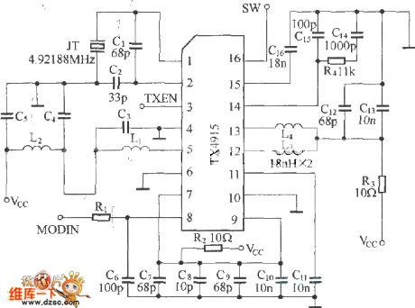
Figure: The remote control emitting circuit composed of TX4915 (View)
View full Circuit Diagram | Comments | Reading(435)
The SF05A/B emitter circuit
Published:2011/6/26 8:21:00 Author:Borg | Keyword: emitter circuit
Figure:The SF05A/B emitter circuit
SF05A/B can work with SJ05B,SJ04E and SJ04H, and the emitting efficiency of the circuit is relevant to the working voltage, aerial and R2. (View)
View full Circuit Diagram | Comments | Reading(373)
The phase-lock function oscillator circuit
Published:2011/6/26 22:35:00 Author:Borg | Keyword: phase-lock, function oscillator
The phase-lock function oscillator circuit is shown in the figure.
(View)
View full Circuit Diagram | Comments | Reading(671)
The reception circuit composed of SJ05B/C
Published:2011/6/26 8:24:00 Author:Borg | Keyword: reception circuit
Figure:The reception circuit composed of SJ05B/C (View)
View full Circuit Diagram | Comments | Reading(360)
The circuit of the emitting component SB-100ATX
Published:2011/6/27 19:58:00 Author:Borg | Keyword: emitting component
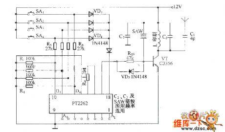
SB-100 is a general remote control component, the model of the emitting component is SB-100ATX, the reception component is SB-100ARX. SB-100ATX is a high stability wireless remote control emitting circuit composed of SAW elements, whose circuit is almost the same with CS900.
Figure: The circuit of the emitting component SB-100ATX The circuit contains a loading oscillator circuit composed of the ultra-high frequency triode C3356 and the SAW element and a emitting encode circuit composed of the digital encoding circuit, see as the figure. SB-100ATX emitting component characterizes stable frequency. (View)
View full Circuit Diagram | Comments | Reading(460)
The SB-50ALTX emitter circuit
Published:2011/6/27 10:01:00 Author:Borg | Keyword: emitter circuit
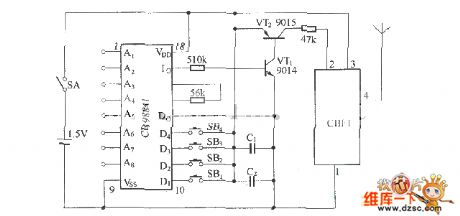
Figure: The SB-50ALTX emitter circuit (View)
View full Circuit Diagram | Comments | Reading(442)
The pulse generating circuit
Published:2011/6/27 10:34:00 Author:Borg | Keyword: pulse generating circuit
View full Circuit Diagram | Comments | Reading(441)
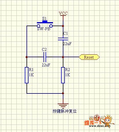
The key pulse reset circuit
Published:2011/6/27 10:36:00 Author:Borg | Keyword: key pulse, reset circuit
View full Circuit Diagram | Comments | Reading(425)
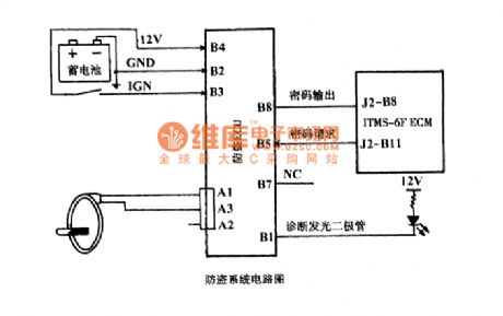
automobile burglary-resisting system circuit
Published:2011/6/14 8:27:00 Author:chopper | Keyword: automobile, burglary-resisting system
View full Circuit Diagram | Comments | Reading(434)
The emitter circuit composed of BA1404
Published:2011/6/25 20:43:00 Author:qqtang | Keyword: emitter circuit
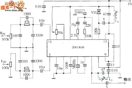
BA1404 is the special integrated circuit of FM stereo sound, as the working feature is good, it is also used in wireless control. BA1404 needs a low power supply voltage, its power is also low, and its structure is completed, it needs a few external elements, and finally, it works stably and reliably. The notes of using BA1404 are listed as follows: (1) to keep the frequency feature of the emitter conforming to that of the FM broadcast receiver, we need to fix a pre-emphasizer whose time constant is 50μs in the left and right channel, see as the figure.
Figure: The emitter circuit composed of BA1404 (View)
View full Circuit Diagram | Comments | Reading(2292)
| Pages:159/195 At 20141142143144145146147148149150151152153154155156157158159160Under 20 |
Circuit Categories
power supply circuit
Amplifier Circuit
Basic Circuit
LED and Light Circuit
Sensor Circuit
Signal Processing
Electrical Equipment Circuit
Control Circuit
Remote Control Circuit
A/D-D/A Converter Circuit
Audio Circuit
Measuring and Test Circuit
Communication Circuit
Computer-Related Circuit
555 Circuit
Automotive Circuit
Repairing Circuit