Signal Processing
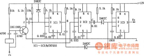
The 4-time frequency circuit composed of CH7555
Published:2011/6/17 7:35:00 Author:Borg | Keyword: frequency circuit | From:SeekIC

In the figure is the 4-time frequency circuit. This circuit consists of 3 CH7555 timers. When the symmetric wave is input, it is turned into the twice frequency by the phase inverter and the transistor. The two signals trigger the CH7555 single circuit at the same time, so that there generates two teams of pulses with different band widths on the output terminals of IC1 and IC2, then their dropping edges are to trigger the single stable circuit consisting of IC3, finally, a four-time frequency is generated on the output terminal of IC3.
Reprinted Url Of This Article:
http://www.seekic.com/circuit_diagram/Signal_Processing/The_4_time_frequency_circuit_composed_of_CH7555.html
Print this Page | Comments | Reading(3)

Article Categories
power supply circuit
Amplifier Circuit
Basic Circuit
LED and Light Circuit
Sensor Circuit
Signal Processing
Electrical Equipment Circuit
Control Circuit
Remote Control Circuit
A/D-D/A Converter Circuit
Audio Circuit
Measuring and Test Circuit
Communication Circuit
Computer-Related Circuit
555 Circuit
Automotive Circuit
Repairing Circuit
Code: