
Index 126
SCR_FOR_HORIZONTAL_OUTPUT
Published:2009/7/20 20:54:00 Author:Jessie
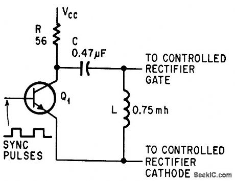
Sync pulses saturate driver Q1, permitting C to charge, for achieving fast turnoff after pate-turnoff scr conducts yoke current for 27 microsec to defect electron beams.-L. D. Shergalis, Scr's for 19-Inch Tv, Electronics, 37:23, p 97-98. (View)
View full Circuit Diagram | Comments | Reading(612)
Current_boost_regulator_for__5_volts_at_4_amperes_with_5_ampere_current_limiting
Published:2009/7/20 20:54:00 Author:Jessie
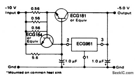
Current boost regulator for -5 volts at 4 amperes with 5-ampere current limiting. When a boost transistor is used short-circuit current is equal to the sum of the series pass and regulator limits, which are measured at 3.2 amperes and 1.8 amperes respectively. Series pass limiting is approximately equal to 0.6 volts/RSC (courtesy GTE Sylvania Incorporated). (View)
View full Circuit Diagram | Comments | Reading(631)
NO_CALIBRATION_OHMMETER
Published:2009/7/20 20:54:00 Author:Jessie
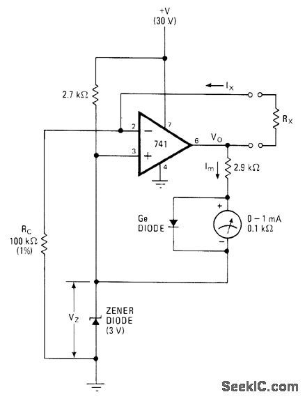
When unknown resistor RX is connected, milliammeter reading is RX/RC where RC is value of known standard resistor used. RX is then equal to meter reading in milliamperes multiplied by value of RC in ohms. Full-scale deflection is thus obtained on 1-mA meter when RX is 100K. Other ranges can be obtained by changing value of RC, using range switch if desired. Meter has automatic zeroing because VO rises to exactly 3 V when measuring leads are shorted and no current flows through meter.-V. Ramprakash, Direct-Reading Ohmmeter Needs No Calibration, Electronics, Nov, 11, 1976, p 115-116. (View)
View full Circuit Diagram | Comments | Reading(700)
CLAMPED_SYNC_SEPARATOR
Published:2009/7/20 20:53:00 Author:Jessie
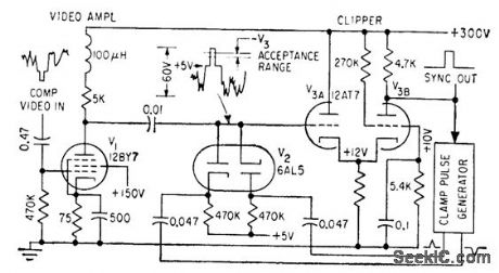
Separates sync from composite input signal at studio, for automatic video level control.-J. O. Schroeder, Holding Video Levels While Switching Studios, Electronics, 32:22, p 96-98.
(View)
View full Circuit Diagram | Comments | Reading(450)
Shunt_regulator+5_voltsusing_an_ECG915_or_ECG915D
Published:2009/7/20 20:48:00 Author:Jessie
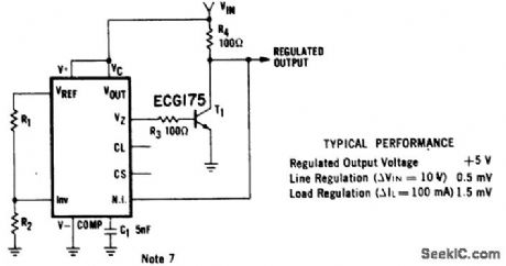
Shunt regulator(+5 volts)using an ECG915 or ECG915D.For a ±5% fixed output resistor R1 is 2.15 ohms and R2 is 4.99 ohms,For metal can applications where Vz is required,a 6.2-volt zener should be connected in series with the regulated output(courtesy GTE Sylvania Incorporated). (View)
View full Circuit Diagram | Comments | Reading(468)
MODULATOR_TRANSFORMER
Published:2009/7/20 23:47:00 Author:Jessie
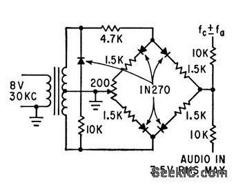
Circuit provides best possible balance between halves of center-tapped secondary, as required for precise phase splitting, in Boynton-Scholt modulator shown.-Wide-Band Transformer Covers 3 Kc to 22 Mc, Electronics, 35:25, p 66. (View)
View full Circuit Diagram | Comments | Reading(543)
XY_RECORDER_SERVO
Published:2009/7/21 1:24:00 Author:Jessie
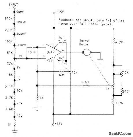
Optical Electronics 9712 FET opamp drives 10-V 0.2-A servomotor used for positioning pen of XY recorder. Circuit provides coarse and fine attenuation of input signal along with position-control pot. FET input of opamp allows use of 1-megohm input attenuator. Response time is limited only by that of servomotor and mechanical portion of system. Requires highly stable regulated power supply.- The 9712 as a Servo Motor Amplifier, Optical Electronics, Tucson, AZ, Application Tip 10206. (View)
View full Circuit Diagram | Comments | Reading(1045)
Full_wave_synchronous_rectification_circuit
Published:2009/7/21 2:12:00 Author:Jessie
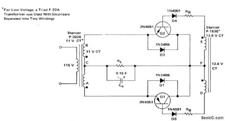
Full-wave synchronous rectification circuit (courtesy Motorola Semiconductor Products Inc.). (View)
View full Circuit Diagram | Comments | Reading(666)
Transducer_linearization_circuit_using_the_433_multiplier_divider_chip
Published:2009/7/21 2:16:00 Author:Jessie
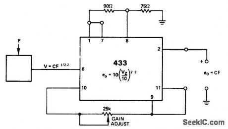
Transducer linearization circuit using the 433 multiplier/divider chip (courtesy Analog Devices, Inc.). (View)
View full Circuit Diagram | Comments | Reading(514)
5AAT__5TO__15_V
Published:2009/7/8 23:17:00 Author:May
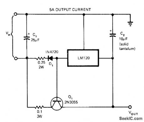
Use of 2N3055 pass transistor boosts current output of LM120 regulator IC. Minimum differential between input and output voltages is typically 2.5 V, so supply voltage must be 2.5 V higher than preset output voltage of regulator chosen from National LM120 series.-C. T. Nelson, Power Distribution and Regulation Can Be Simple, Cheap and Rugged, EDN Magazine, Feb, 20, 1973, p 52-58. (View)
View full Circuit Diagram | Comments | Reading(688)
CONVERTING_TO_DUAL_SUPPLY
Published:2009/7/8 23:16:00 Author:May
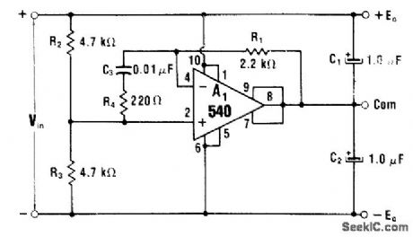
With equal values for R2 and R3, input of 30 V is converted to ±15 V at output. If desired, R2 and R3 can be scaled for unequal voltage drops. Circuit uses 540 power IC having 100-mA rating for each out-put, for handling load imbalances up to 100 mA.-W. G. Jung, IC Op-Amp Cookbook, Howard W. Sams, Indianapolis, IN, 1974, p 170-171. (View)
View full Circuit Diagram | Comments | Reading(604)
Line current restrictor circuit diagram
Published:2011/8/2 2:24:00 Author:Rebekka | Keyword: Line current restrictor

The figure shows the current of the line current restrictor limit circuit. Once the value of the current exceeds the limit value, the controller relay will cut off the power supply immediately. The current limit value is continuously adjustable from l00mA to 10A. The components of the circuit is shown as above. The whole circuit includs the line current sample and voltage comparator, RS flip-flop and control relay. It is composed of an operational amplifier MA741 and a four - two input NAND gate CD4011. (View)
View full Circuit Diagram | Comments | Reading(857)
Cosine_function_from_the_4301_multifunction_chip
Published:2009/7/21 2:47:00 Author:Jessie
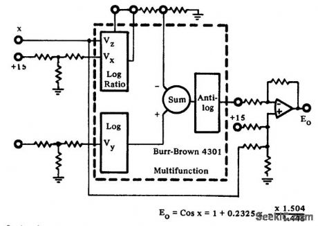

Cosine function from the 4301 multifunction chip (courtesy Burr-Brown Research Corporation). (View)
View full Circuit Diagram | Comments | Reading(584)
Uninterrupted power supply circuit composed of MIC5158
Published:2011/8/2 2:25:00 Author:Rebekka | Keyword: Uninterruptible power supply
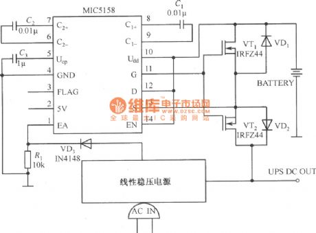
Uninterrupted power supply circuit composed of MIC5158 is shown as above. The circuit uses MIC5158 to control the uninterrupted power supply which formed by the source electrode of two N-channel tubes. The source electrodes of the 2 N-channel tubes are connected. This can avoid the current from passing the internal diode of integrated voltage regulator. This kind of low dropout regulator can control the battery switch rapidly. The most critical function of the exchange network line monitor is to the output voltage is lower than the designed limiting voltage when the batterr works online. (View)
View full Circuit Diagram | Comments | Reading(720)
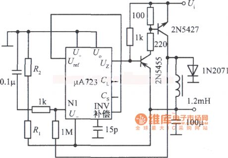
Negative pressure switch regulated power supply circuit diagram
Published:2011/8/2 2:26:00 Author:Rebekka | Keyword: Negative pressure switch, Vacuum switch regulated power supply
View full Circuit Diagram | Comments | Reading(856)
±5 to ±l8V adjustable tracking regulated power supply circuit diagram
Published:2011/5/10 2:30:00 Author:Rebekka | Keyword: regulated power supply

View full Circuit Diagram | Comments | Reading(664)
Multiple centralized control regulated power supply circuit diagram
Published:2011/8/2 1:27:00 Author:Rebekka | Keyword: Multiple centralized control, regulated power supply
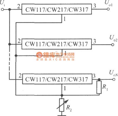
Multiple centralized control regulated power supply circuit composed of multiple three-terminal adjustable integrated voltage regulators is shown as above.
The figure shows the integrated centralized control of multiple power supply composed of a number of three-terminal adjustable regulators. All the input terminals of the integrated voltage regulators is connected togetherand they share the same power supply. All the adjustment terminals are connected together. The resistance Rl and R2 control the output voltage. For keeping the output voltage deviation of each integrated regulator is less than 100mV, the load current of each printed circuit board should be less than 10mA. Otherwise, the output voltage deviation will be significantly increased. (View)
View full Circuit Diagram | Comments | Reading(585)
0 to 20V 1A adjustable regulated power supply circuit diagram
Published:2011/5/10 2:30:00 Author:Rebekka | Keyword: adjustable regulated power supply

0 to 20V 1A adjustable regulated power supply circuit diagram composed of LM120-15 and zener diode LM741. (View)
View full Circuit Diagram | Comments | Reading(721)
Tracking integrated power supply circuit composed of two CW117 CW217 CW317
Published:2011/8/3 2:40:00 Author:Rebekka | Keyword: Tracking integrated power supply

View full Circuit Diagram | Comments | Reading(493)
The morning and night light-operated switch circuit diagram with 10-10LX light intensity
Published:2011/8/3 2:42:00 Author:Rebekka | Keyword: morning and night , light-operated switch , 10-10LX light intensity
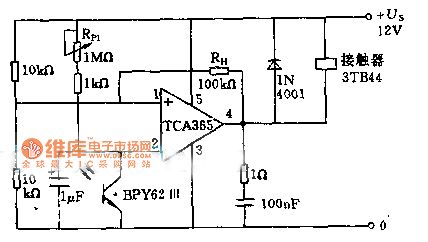
The power of 8.5KW load off can be controlled by using the input phototransistor BPY62 and power operational amplifier.The voltage divider composed of two 10KΩ resistors connects to the inverting input terminal of the voltage divider, so that the turnover voltage of the amplifiers is 1/2 US. Switch sensitivity can be adjusted in the range of 10 - 10 quadruplicate lx by using potentiometer. The output of the circuit is controlled by contactor coil. (View)
View full Circuit Diagram | Comments | Reading(1491)
| Pages:126/291 At 20121122123124125126127128129130131132133134135136137138139140Under 20 |
Circuit Categories
power supply circuit
Amplifier Circuit
Basic Circuit
LED and Light Circuit
Sensor Circuit
Signal Processing
Electrical Equipment Circuit
Control Circuit
Remote Control Circuit
A/D-D/A Converter Circuit
Audio Circuit
Measuring and Test Circuit
Communication Circuit
Computer-Related Circuit
555 Circuit
Automotive Circuit
Repairing Circuit