
Index 137
BATTERY_BACKUP
Published:2009/7/5 20:36:00 Author:May
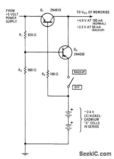
Delivers 2.3 V to microprocessor memory automatically in event of supply failure, to prevent loss of data. On standby, batteries receive charge of about 20 mA through R3 and Q1. When power supply fails, Q1 isolates it from load and Q2, conducts to provide changeover to battery power. Standby switch (optional) permits defeating battery backup.-R.N. Bennett, 2.4-V Battery Backup Protects Microprocessor Memory, Electronics, Feb. 3, 1977, p 109; reprinted in Circuits for Electronics Engineers, Electronics, 1977, p 304. (View)
View full Circuit Diagram | Comments | Reading(0)
H_bridge_dc_motor_controller
Published:2009/7/23 22:55:00 Author:Jessie

Figure 7-2 shows a MAX620 driving an H-bridge switch that controls the direction of a +5-Vdc motor. By toggling between the forward and reverse inputs, each driver-output pair turns on the associated pair, which passes current through the motor, causing rotation in the desired direction. To prevent all four MOSFEEs from switching on at once, update the forward/reverse inputs before clocking CE low, and do not assert forward and reverse simultaneously. Do not use a supply that will cause the gate drive to exceed the absolute maximum gate-to-source voltage of the low-side switch. MAXIM NEW RELEASES DATA Book, 1992, P. 4-27. (View)
View full Circuit Diagram | Comments | Reading(2091)
Linear_regulator_with_selectable_output
Published:2009/7/23 22:55:00 Author:Jessie
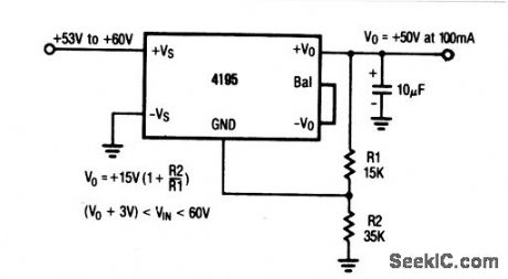
The output of this regulator can be set to any value between + 15 V and +50 V by means of voltage-divider resistors R1 and R2 (as shown by the equations). Connection information is shown in Fig. 7-3B. (View)
View full Circuit Diagram | Comments | Reading(605)
Dual_linear_regulator_with_balanced_output
Published:2009/7/23 22:55:00 Author:Jessie
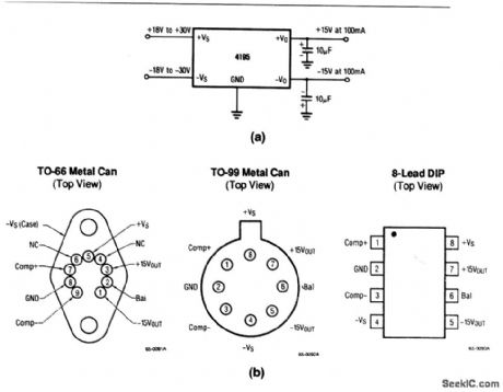
This circuit converts 18 V to +30-V input into regulated ±15-V outputs. Note that a minimum of external components (two 10-μF capacitors) are needed to complete the circuit. Figure 7-3A shows the connection information for TO-66, TO-99, and 8-lead DIP packages. (View)
View full Circuit Diagram | Comments | Reading(820)
Ultra_low_power_FM_radio_receiver
Published:2009/7/23 22:23:00 Author:Jessie
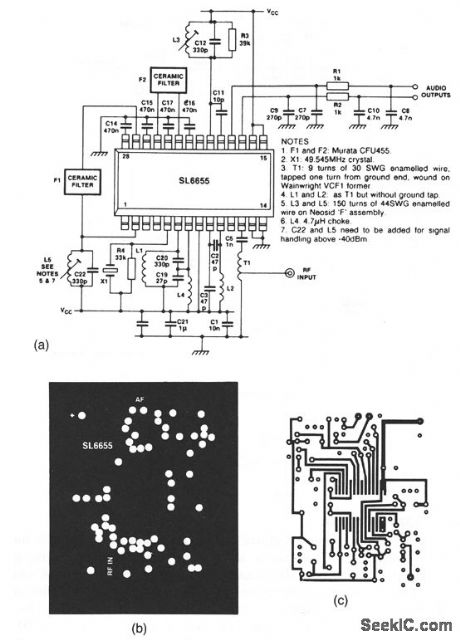
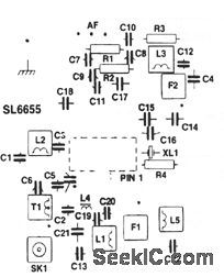
The SL6655 shown in this circuit is a single-chip RF amplifier/mixer/oscillator/IF amplifier/detector,operating with a 0.95-to 5-V Supply at a typicalcurrent of 1 mA.Typical sensitivity is 250 nV, with atypical audio output of 12 mV(rms).The circuit can operate at frequencies up to 100 MHz. Circuit values for 50-MHz operation are shown.Typical surface-mount construction details areshown in Figs. 2-34B(ground plane),2-34C(copper track),and 2-34D(component overlay)(all 1:1). (View)
View full Circuit Diagram | Comments | Reading(987)
Buck_boost_voltage_regulator
Published:2009/7/23 22:35:00 Author:Jessie
A disadvantage of the standard step-up and stop-down circuits is the limitation of the input voltage range. For a step-up circuit (Fig. 4-2), the battery voltage must always be less than the programmed output voltage, and for a step-down circuit (Fig. 4-3), the battery voltage must always be greater than the output voltage. Figure 4-8 eliminates this disadvantage, and allows a battery voltage above the programmed output voltage to decay to well below the output voltage. The values of R2 and R3 are determined, as described for Fig. 4-2. (View)
View full Circuit Diagram | Comments | Reading(740)
Bootstrap_voltage_regulator
Published:2009/7/23 22:34:00 Author:Jessie

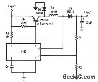
In this circuit, power to the IC is taken from the output voltage by connecting the +Vs pin and the top of R1 to the output voltage. Notice that the initial battery voltage must be greater than 3.0 V when the circuit is energized. If not, there will not be enough voltage at pin 5 to start the IC. The big advantage of this circuit is the ability to operate down to a discharged battery voltage of 1.0 V.The value of C1 is determined, as described for Fig. 4-2. (View)
View full Circuit Diagram | Comments | Reading(779)
ADAPTIVE_REFRESH
Published:2009/7/3 4:36:00 Author:May
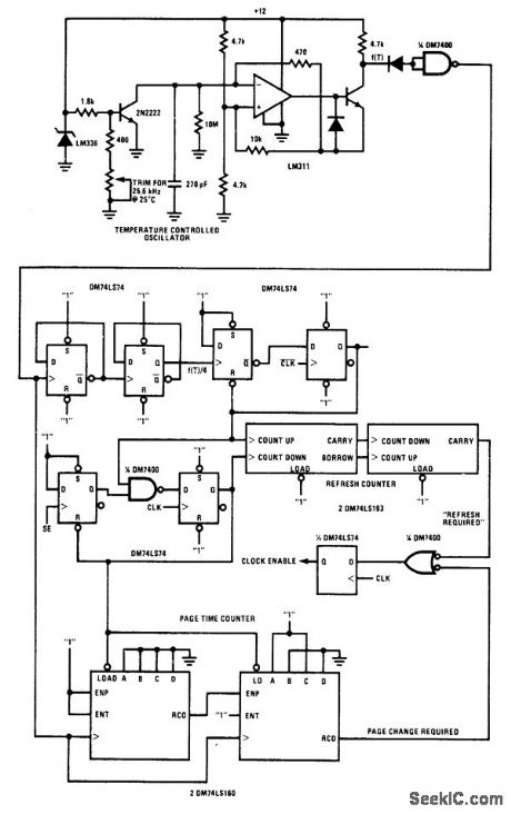
Circuit monitors system utilization of National MM2464 64-kilobit charge-coupled device (CCD). Refresh time and maximum page times are determined by two counters that obtain clock signals from temperature-controlled oscillator.- Memory Applications Handbook, National Semiconductor, Santa Clara, CA, 1978, p 7-1-7-10. (View)
View full Circuit Diagram | Comments | Reading(650)
Basic_step_up_voltage_regulator
Published:2009/7/23 22:28:00 Author:Jessie
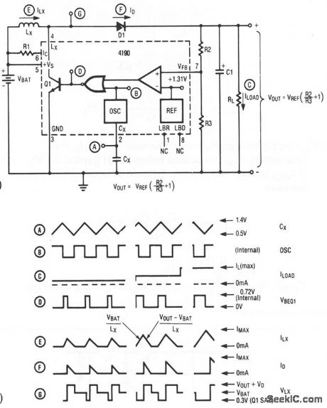
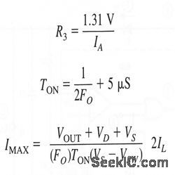
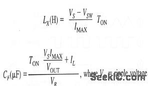
Figures 4-2A and 4-2B show a basic step-up voltage regulator, and waveforms, respectively. Component values are tailored to circuit requirements, as follows:
where: IA feedback divider current (typically 50 to 100 μA)where: Vs =supply voltage, VD= diode forward voltage, IL= dc load current, VSW= sauration voltage of Q 1 (typical 0.5 V), If IMAX is more than 375 mA, Q1 must be replaced with a power transistor.
(View)
View full Circuit Diagram | Comments | Reading(735)
FET_SUPPLIES_CONSTANT_CURRENT
Published:2009/7/23 22:27:00 Author:Jessie
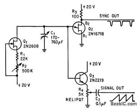
Utilizes near-zero temperature drift of fet at bias point, to make performance independent of battery or line voltage fluctuations.-E. Elad, FET Insures Stable Sawtooth Wave, Electronics, 39:16, p 122-123. (View)
View full Circuit Diagram | Comments | Reading(570)
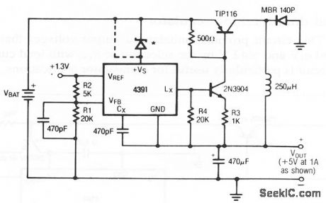
STEP_UP_SWITCHING_REGULATOR_FOR_6_V_BATTERY
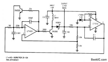
Published:2009/7/3 4:27:00 Author:May
View full Circuit Diagram | Comments | Reading(782)
High_output_dual_tracking_regulator
Published:2009/7/23 22:48:00 Author:Jessie
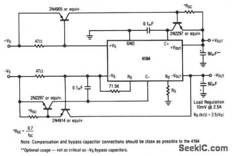
This circuit provides balanced output voltage with a load regulation of 10mV at .5A. (View)
View full Circuit Diagram | Comments | Reading(789)
High_power_step_up_voltage_regulator
Published:2009/7/23 22:31:00 Author:Jessie
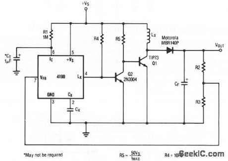
Figure 4-4 shows a step-up regulator for loads up to values are tailored to circuit requirements, as described for Fig. 4-2, except for R4 And R5, as shown. (View)
View full Circuit Diagram | Comments | Reading(855)
Basic_step_down_voltage_regulator
Published:2009/7/23 22:29:00 Author:Jessie
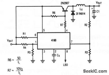
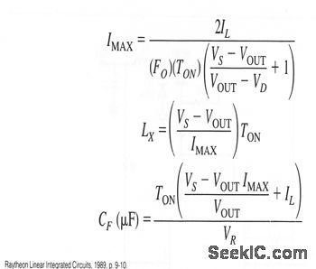
Figure 4-3 shows a basic step-down voltage regulator, where loads are from 500 mW to 2 W. Component values are tailored to circuit requirements, as described for Fig. 4-2, except as:.
(View)
View full Circuit Diagram | Comments | Reading(644)
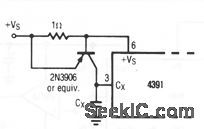
Positive_negative_dual_tracking_power_supply
Published:2009/7/23 22:40:00 Author:Jessie
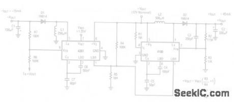
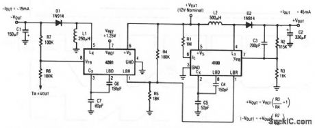
This circuit uses the 4190 as a step-up regulator and the 4391 as an inverter. The supply is capable of delivering +45 mA (15 mA with regulation) until the battery decays below 5.0V. Output voltage ripple is under 100 mVpp at ± 15-V output. (View)
View full Circuit Diagram | Comments | Reading(715)
High_power_step_down_voltage_regulator
Published:2009/7/23 22:43:00 Author:Jessie
This circuit shows a stop-down regulator for loads up to 5 W. Notice that a minimum load of at least 1 mA must be connected when the circuit is energized. (View)
View full Circuit Diagram | Comments | Reading(643)
Basic_inverting_voltage_regulator
Published:2009/7/23 22:42:00 Author:Jessie
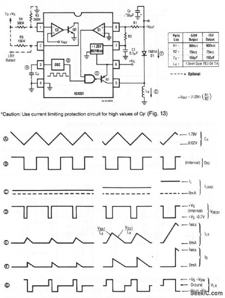
Figures 4-12A and 4-12B show a basic inverting voltage regulator and waveforms, respectively. The outputs are -5 or -15 V, using the values shown.Other outputs can be selected by changing R1 and R2. It may be necessary to change other circuit values. If high values of CF are used, a current-limiting protection circuit (Fig. 4- 12C) might be required. (View)
View full Circuit Diagram | Comments | Reading(588)
Battery_life_extender
Published:2009/7/23 22:33:00 Author:Jessie
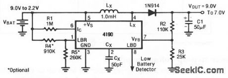
This circuit extends the lifetime of a 9-V battery. The regulator remains in a quiescent state (drawing only 215 μA) until the battery voltage decays below 7.5 , at which time the circuit starts to switch and regulate the output at 7.0 V until the battery falls below 2.2 V. If this circuit is operated at a typical 80% efficiency with an output current of 10 mA, at 5.0-V battery voltage, the average input current is 17.5 mA. (View)
View full Circuit Diagram | Comments | Reading(0)
Step_down_voltage_regulator_for_inputs_greater_than_30_V
Published:2009/7/23 22:32:00 Author:Jessie
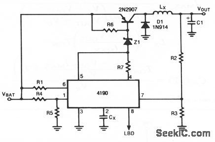
Component values are tailored to circuit requirements as described for Fig. 4-2. Adding the zener allows battery voltage to increase by the zener value. For example, if a 24-V zener is used, maximum battery voltage can go to 48 V.However, addition of the zener does not alter the maximum charge of supply. With a 24-V zener, the circuit stops when battery voltage drops below 24 V + 2.2 V= 26.2V. (View)
View full Circuit Diagram | Comments | Reading(597)
Step_down_regulator_with_short_circuit_protection
Published:2009/7/23 22:39:00 Author:Jessie
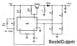
With this circuit, the low-battery detector (LBD) is connected to sense the output voltage, and shuts off the oscillator by forcing pin 2 low if the output voltage drops. Component values are tailored to circuit requirements, as described in Fig. 4-2, except: choose resistor values so that R5= R3 and R4= R2, and make R8 25 to 35 times higher than R3. (View)
View full Circuit Diagram | Comments | Reading(544)
| Pages:137/291 At 20121122123124125126127128129130131132133134135136137138139140Under 20 |
Circuit Categories
power supply circuit
Amplifier Circuit
Basic Circuit
LED and Light Circuit
Sensor Circuit
Signal Processing
Electrical Equipment Circuit
Control Circuit
Remote Control Circuit
A/D-D/A Converter Circuit
Audio Circuit
Measuring and Test Circuit
Communication Circuit
Computer-Related Circuit
555 Circuit
Automotive Circuit
Repairing Circuit