
Index 136
Positive and negative output voltage tracking regulated power supply integrated circuit diagram 2
Published:2011/5/10 1:36:00 Author:Rebekka | Keyword: Positive and negative output voltage tracking, regulated power supply

Here is the diagram 2of positive and negative output voltage tracking regulated power supply integrated circuit composed of CW117, CW217 and CW317. (View)
View full Circuit Diagram | Comments | Reading(620)
Voltage_controlled_current_source
Published:2009/7/23 21:50:00 Author:Jessie
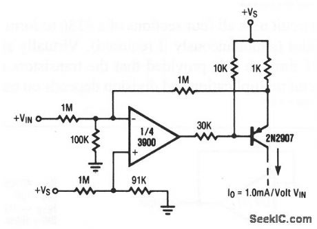
This circuit provides a variable current that is controlled by input voltage +VIN The circuit is sometimes called a transconductance amplifier, and is similar to the OTAs (operational transconductance amplifiers) that are described in chapter 11. (View)
View full Circuit Diagram | Comments | Reading(0)
Multiple regulated power supply circuit composed of LM341-5 and LM326H
Published:2011/5/10 1:09:00 Author:Rebekka | Keyword: Multiple regulated power supply circuit

View full Circuit Diagram | Comments | Reading(740)
Light control regulated power supply circuit diagram composed of CW7900
Published:2011/5/10 1:10:00 Author:Rebekka | Keyword: Light control regulated power supply
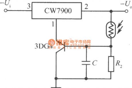
Light control circuit power supply circuit composed of CW7900(the output voltage increases in illumination). (View)
View full Circuit Diagram | Comments | Reading(557)
POWER_SUPPLY_MONITOR
Published:2009/7/5 22:47:00 Author:May
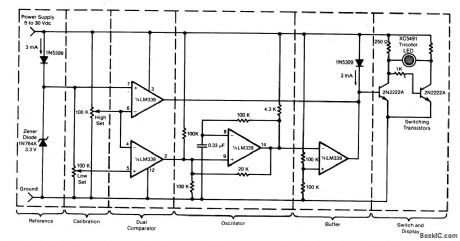
Circuit Notes
This circuit uses a tricolor LED display to indicate acceptable and unacceptable output voltages. One to set the upper voltage limit, the other, the lower voltage limit. When the monitored voltage is above the set maximum, the LED display turns red. Yellow turns on for voltages below the set minimum, and green turns on for voltages between the high and the low settings. The circuit does not need a separate power supply. It is powered by the voltage it monitors.The circuit can be adapted to monitor voltage differences between two power supplies. Should the monitored voltages differ by more than a set value, a visual or an audible alarm would warn the operator about the difference.The circuit can also be modified for remote monitoring and the use of a separate power supply. (View)
View full Circuit Diagram | Comments | Reading(0)
Dual-symmetric regulated power supply circuit composed of RC4194TK and RC4194D
Published:2011/5/10 1:10:00 Author:Rebekka | Keyword: Dual-symmetric regulated power supply

Dual-symmetric regulated power supply circuit composed of RC4194TK and RC4194D. (View)
View full Circuit Diagram | Comments | Reading(1073)
Multiple regulated power supply circuit composed of LM340 series
Published:2011/5/10 1:10:00 Author:Rebekka | Keyword: Multiple regulated power supply circuit

View full Circuit Diagram | Comments | Reading(656)
12V 10A regulated power supply circuit composed of LM340K-12
Published:2011/6/23 4:26:00 Author:Rebekka | Keyword: regulated power supply

View full Circuit Diagram | Comments | Reading(2592)
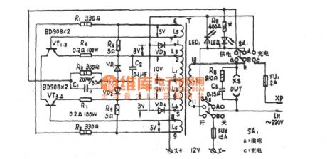
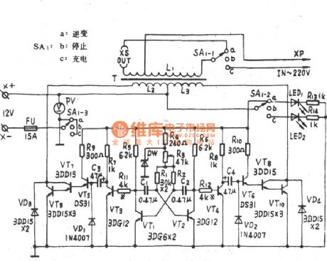
150W integrated circuit transistor hybrid emergency power supply circuit diagram
Published:2011/6/23 4:25:00 Author:Rebekka | Keyword: integrated circuit transistor, hybrid emergency power supply

150W integrated circuit transistor hybrid emergency power supply circuit diagram. (View)
View full Circuit Diagram | Comments | Reading(1134)
ZJ-100VA emergency power supply circuit diagram
Published:2011/5/10 1:18:00 Author:Rebekka | Keyword: emergency power supply
ZJ-100VA emergency power supply circuit diagram. (View)
View full Circuit Diagram | Comments | Reading(516)
TJ-3-100 emergency power supply circuit diagram
Published:2011/5/10 1:34:00 Author:Rebekka | Keyword: emergency power supply
TJ-3-100 emergency power supply circuit diagram. (View)
View full Circuit Diagram | Comments | Reading(515)
CLOCK_SOURCE_
Published:2009/7/5 22:29:00 Author:May
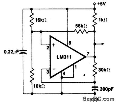
A clock source using LM311 voltage comparator in positive feedback mode to minimize clock frequency shift problem. (View)
View full Circuit Diagram | Comments | Reading(1775)
A_C_TO_D_C_CURRENT_STANDARDIZATION
Published:2009/7/23 22:04:00 Author:Jessie
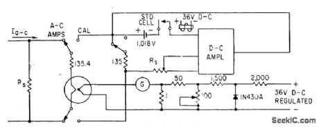
Used to standardize alternating currents directly to standard cell-E. A. Gilbert, Feed-back Circuits for A-C Instrument Calibration, Electronics, 33:40, p 94-96. (View)
View full Circuit Diagram | Comments | Reading(508)
HIGH_VOLTAGE_SUPPLY
Published:2009/7/5 21:44:00 Author:May

Circuit NotesA 6 V battery can provide 100-150 Vdc center-tapped at a high internal impedance (not dangerous though it can inflict an unpleasant jolt). A 6.3 V transformer is connected in reverse with a transistor used in a Hartley oscillator configuration. The frequency of operation may be controlled by varying the value of the 10 K ohm resistor. The 10 μF capacitor must have a working voltage of at least 250 Vdc. (View)
View full Circuit Diagram | Comments | Reading(0)
HIGH_VOLTAGE_GEIGER_COUNTER_SUPPL
Published:2009/7/5 21:38:00 Author:May
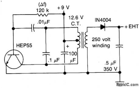
Circuit NotesThis circuit will generate about 300 volts dc-at a very low current,but enough for a GMtube. (View)
View full Circuit Diagram | Comments | Reading(0)
SIMPLE_HIGH_VOLTAGE_SUPPLY
Published:2009/7/5 21:37:00 Author:May
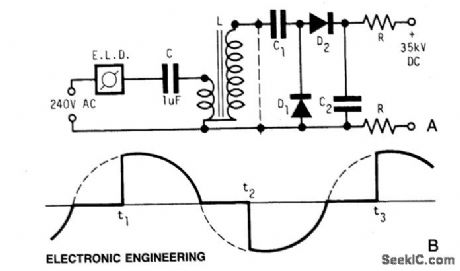
Circuit NotesA light dimmer, a 1 μF capacitor and a 12 V car ignition coil form the simple line powered HV generator. The current in the dimmer is shown in Fig. B. At times t1, t2,..., set by the dimmer switch, the inner triac of the dimmer switches on, and a very high and very fast current pulse charges the capacitor through the primary of the induction coil. Then at a rate of 120 times per second for a 60 Hz line, a very high voltage pulse appears at the secondary of the coil. To obtain an HV dc output, use a voltage doubler. D1 and D2 are selenium rectifiers (TV 18 Siemens or ITT) used for the supply of television sets. High value output shock protection resistors, R, are recommended when suitable. (View)
View full Circuit Diagram | Comments | Reading(0)
Single_chip_power_supply_with_linear_regulation
Published:2009/7/23 22:59:00 Author:Jessie
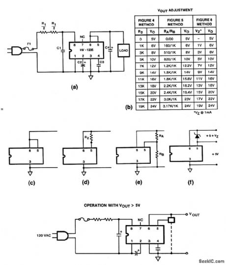
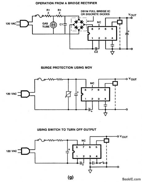
The HV-1205 converts ac into regulated dc to power low-voltage components, such as ICs. Input voltage is 120 V at frequencies from 48 to 380 Hz. Output voltage is set by selection of external components, as shown in the table of Fig. 7-6B, and it can be any value between 5 V and 24V, at 50 mA. Recommended values for components shown in Figs. 7-6C through 7-6G are as follows: fuse F1 is 1/4 A, 2AG; source resistor R1=150 Ω; snubber capacitor C1=0.05μF, ac rated; metal-oxide varistor (MOV, Fig. 7-6G) surge suppressor =V130LA20 or equivalent; pre-regulator capacitor C2 =470μF, with a voltage rating about 10-V greater than chosen VOUT; inhibit capacitor C3=150 pF for 50/60 Hz, and 47 pF for 400 Hz, with a voltage rating about 10-V greater than chosen VOUT; output filter capacitor C4=1μF minimum, 100μF reduced output spikes to about 25 mVp p-p; R2, RA, RB, and VZ=values shown in table Fig. 7-6B (VOUT adjustment). Note that the HV-1205 does not provide isolation from the line. (View)
View full Circuit Diagram | Comments | Reading(889)
Four_phase_stepper_motor_drive_system
Published:2009/7/23 22:57:00 Author:Jessie
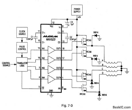
Figure 7-3 shows a MAX620 connected to form a complete stepper-motor drive. TTL/CMOS signals from the logic network are translated to high-side levels that drive four N-channel power MOSFETs, supplying current to each of four stepper-motor phases. The diodes provide a discharge current path for the stepper-motor windings. MAXIM NEW RELEASES DATA BOOk, 1992, P. 4-28. (View)
View full Circuit Diagram | Comments | Reading(1572)
Dual_linear_regulator_with_high_output_current
Published:2009/7/23 22:56:00 Author:Jessie
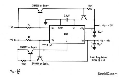
This circuit provides a +15-V and a -15-V output, both of which are capable of delivering 2.5 A. Load regulation is 10 mV at full load. Connection information is shown in Fig. 7-3B. (View)
View full Circuit Diagram | Comments | Reading(597)
Digitally_controlled_dual_tracking_regulator
Published:2009/7/23 22:56:00 Author:Jessie
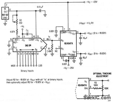
This circuit provides balanced output voltages that can be set by binary inputs applied to the DAC. Outputs vary between 0 and± 19.92 V at loads of ±200 mA.
(View)
View full Circuit Diagram | Comments | Reading(539)
| Pages:136/291 At 20121122123124125126127128129130131132133134135136137138139140Under 20 |
Circuit Categories
power supply circuit
Amplifier Circuit
Basic Circuit
LED and Light Circuit
Sensor Circuit
Signal Processing
Electrical Equipment Circuit
Control Circuit
Remote Control Circuit
A/D-D/A Converter Circuit
Audio Circuit
Measuring and Test Circuit
Communication Circuit
Computer-Related Circuit
555 Circuit
Automotive Circuit
Repairing Circuit