
Index 131
0_1200_V_REGULATED_SUPPLY_FOR_RHOTOMULTIPLIER
Published:2009/7/21 4:54:00 Author:Jessie
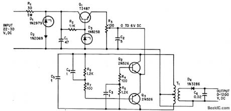
Silicon diodes in R-C filter network gives 0.2% regulation over entire d-c output range, with temperature cosfficient only 0.1% of output voltage per deg C, for photomultiplier stage in airborne equipment. –J. G. Peddie, Network Filters Stabilize d-c Supply Over Wide Range, Electronics, 37:18, p 83. (View)
View full Circuit Diagram | Comments | Reading(587)
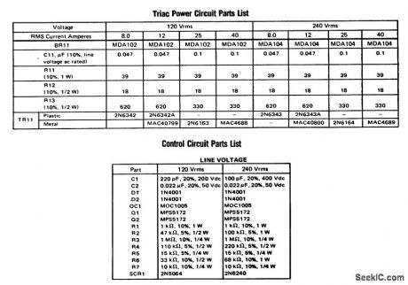
RMS_regulator_for_a_DC_power_supply_using_a_triac_phototransistor_and_UJT
Published:2009/7/21 4:51:00 Author:Jessie
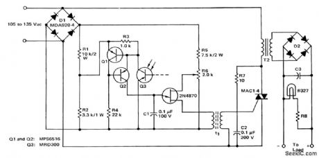
RMS regulator for a DC power supply using a triac, phototransistor and UJT (courtesy Motorola Semiconductor Products Inc.). (View)
View full Circuit Diagram | Comments | Reading(1732)
Triac_static_motor_starting_switch_for_05_HP_115_volt_AC_single_phase_induction_motors
Published:2009/7/21 5:22:00 Author:Jessie

Triac static motor-starting switch for 0.5 HP 115-volt AC single-phase induction motors (courtesy Motorola Semiconductor Products Inc.). (View)
View full Circuit Diagram | Comments | Reading(1752)
Logic_to_inductive_load_interface_using_an_MOC3011_optically_coupled_triac_driver
Published:2009/7/21 5:21:00 Author:Jessie

Logic to inductive load interface using an MOC3011 optically coupled triac driver (courtesy Motorola Semiconductor Products Inc.). (View)
View full Circuit Diagram | Comments | Reading(7108)
Line_voltage_compensation_circuit_using_UJT_trigger_for_a_thyrister_gate
Published:2009/7/21 5:19:00 Author:Jessie
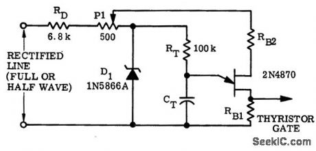
Line-voltage compensation circuit using UJT trigger for a thyrister gate (courtesy Motorola Semiconductor Products Inc.). (View)
View full Circuit Diagram | Comments | Reading(755)
SCR_model__railroading_control
Published:2009/7/21 5:19:00 Author:Jessie
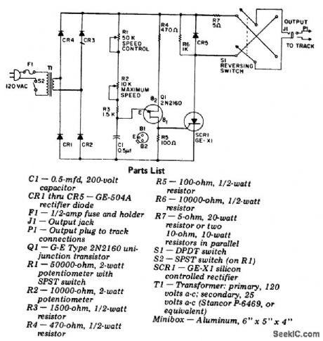
SCR model -railroading control. Bridge circuit CR1 through CR4 supplies pulsating DC to firing circuit Q1, R1 through R5 and C1, which phase controls SCR1. The SCR is in series with the train power and thereby controls the amount of current it receives (courtesy General Electric Company). (View)
View full Circuit Diagram | Comments | Reading(1314)
Triac_trigger_using_an_LM3909_chip
Published:2009/7/21 5:13:00 Author:Jessie

Triac trigger using an LM3909 chip. This circuit operates from a 5-volt logic supply and provides gate trigger pulses of up to 200 mA. The LM3909 provides a 10μs pulse at about a 7 kHz rate. This is not the synchronized zero crossing type since the first trigger could occur at any time; however, the repetition rate is such that after the first cycle, a triac is triggered within 8 volts of zero with a resistive load and a 115-volt AC line. The Sprague transformer provides 2-to-1 stepup (courtesy National Semiconductor Corporation). (View)
View full Circuit Diagram | Comments | Reading(684)
Motor_control_circuitry_using_3650_optical_isolation_amplifiers
Published:2009/7/21 5:12:00 Author:Jessie

Motor control circuitry using 3650 optical isolation amplifiers (courtesy Burr-Brown Research Corporation). (View)
View full Circuit Diagram | Comments | Reading(566)
5_KV_A_F_PENTODE_OSCILLATOR_CRT_SUPPLY
Published:2009/7/21 5:10:00 Author:Jessie

Pentode audio oscillator uses simplified circuit to furnish only second anode potential for crt. –NBS, Handbook Preferred Circuits Navy Aeronautical Electronic Equipment, Vol.1, Electron Tube Circuits, 1963, p N14-4. (View)
View full Circuit Diagram | Comments | Reading(610)
GEIGER_MULLER_SUPPLY
Published:2009/7/21 5:43:00 Author:Jessie

Uses blocking oscillator to provide three stabilized levels of high voltage, at 900, 1,000, and 1,100 V, for G-M tube. Corona discharge tubes are switched in to provide regulation.-F. E. Armstrong, Battery Powered Portable Scaler, Electronics, 33:19, p 74-75. (View)
View full Circuit Diagram | Comments | Reading(942)
Thyrister_half_wave_control_circuit_with_UJT_trigger_designed_for_a_600_ohm_load
Published:2009/7/21 5:42:00 Author:Jessie

Thyrister half-wave control circuit with UJT trigger designed for a 600-ohm load (courtesy Motorola Semiconductor Products Inc.). (View)
View full Circuit Diagram | Comments | Reading(2071)
Plug_in_speed_control_for_tools_and_appliances
Published:2009/7/21 5:41:00 Author:Jessie

Plug-in speed control for tools and appliances. Do not use this control on motors without commutators (courtesy General Electric Company). (View)
View full Circuit Diagram | Comments | Reading(698)
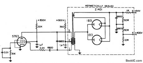
7_KV_A_F_PENTODE_OSCILLATOR_CRT_SUPPLY
Published:2009/7/21 5:40:00 Author:Jessie
Pentode feeds hermetically sealed unit containing transformer, paralleled 1B3's, and filter.-NBS, Handbook Preferred Circuits Navy Aeronautical Electronic Equipment, Vol. 1, Electron Tube Circuits, 1963, p N14-4. (View)
View full Circuit Diagram | Comments | Reading(659)
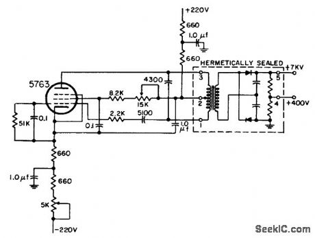
7_KV_OSCILLATOR_TYPE_CRT_SUPPLY
Published:2009/7/21 5:38:00 Author:Jessie

Audio oscillator provides screen-grid voltage for crt directly and second-anode voltage through high-voltage transformer and rectifier-filter.-NBS, Handbook Preferred Circuits Navy Aeronautical Electronic Equipment, Vol. 1, Electron Tube Circuits, 1963, p N14-2. (View)
View full Circuit Diagram | Comments | Reading(644)
Half_wave_variable_AC_control_for_small_motors_and_lamps
Published:2009/7/21 5:38:00 Author:Jessie


Half-wave variable AC control for small motors and lamps. In the lamp position the SCR is controlled by P1. In the motor position and with S2 open the circuit incorporates a feedback feature that maintains a constant motor speed as the load changes. Do not use this circuit for controlling fluorescent lamps, transformers, AC motors with capacitor start, induction motors, shaded pole motors and the like. The motor controlled must have a commutator as found in DC or AC-DC universal motors (courtesy General Electric Company). (View)
View full Circuit Diagram | Comments | Reading(853)
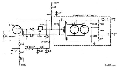
PENTODE_7_KV_A_F_OSCILLATOR_TYPE_CRT_SUPPLY
Published:2009/7/21 5:37:00 Author:Jessie
Example of 1958 circuit design, in which transformer, rectifiers, and filter are hermetically sealed in metal container. Oscillator frequency can be anywhere in range from 1 kc to 100 kc.-NBS, Handbook Preferred Circuits Navy Aeronautical Electronic Equipment, Vol. 1, Electron Tube Circuits, 1963, p N14-2. (View)
View full Circuit Diagram | Comments | Reading(565)
DUAL_TRIODE_7_KV_CRT_SUPPLY
Published:2009/7/21 5:36:00 Author:Jessie

Serves as high-voltage source for screen grid and final anode of 5 to 12-inch cathode-ray tubes.CR1 and CR2 are each six 1N588 silicon diodes in series. Operating frequency is about 450 cps for twin-triode tuned-plate oscillator having high L-C ratio.-NBS, Hand-book Preferred Circuits Navy Aeronautical Electronic Equipment, Vol. I, Electron Tube Circuits, 1963, PC 6, p 6-2. (View)
View full Circuit Diagram | Comments | Reading(713)
Triac_solid_state_relay_circuit_for_AC_power_control
Published:2009/7/21 5:33:00 Author:Jessie

Triac solid-state relay circuit for AC power control. The input circuit will function over the range of 3 to 33 volts (courtesy Motorola Semiconductor Products Inc.). (View)
View full Circuit Diagram | Comments | Reading(1551)
MOS_to_AC_load_interface_using_an_MOC3011_optically_coupled_triac_driver
Published:2009/7/21 6:08:00 Author:Jessie

MOS to AC load interface using an MOC3011 optically coupled triac driver (courtesy Motorola Semiconductor Products Inc.). (View)
View full Circuit Diagram | Comments | Reading(1784)
High_intensity_lamp_dimmer_or_fan_control
Published:2009/7/21 6:06:00 Author:Jessie
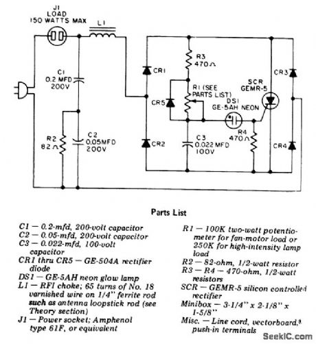
High-intensity lamp dimmer or fan control. This circuit is for use with high-intensity lamps with a built-in transformer only; do not use with 120-volt standard household incandescent or fluorescent lamps. Fan motors should not draw more than 1.5 amperes (courtesy General Electric Company). (View)
View full Circuit Diagram | Comments | Reading(2214)
| Pages:131/291 At 20121122123124125126127128129130131132133134135136137138139140Under 20 |
Circuit Categories
power supply circuit
Amplifier Circuit
Basic Circuit
LED and Light Circuit
Sensor Circuit
Signal Processing
Electrical Equipment Circuit
Control Circuit
Remote Control Circuit
A/D-D/A Converter Circuit
Audio Circuit
Measuring and Test Circuit
Communication Circuit
Computer-Related Circuit
555 Circuit
Automotive Circuit
Repairing Circuit