
Electrical Equipment Circuit
Index 34
4_channel_analog_data_selector
Published:2009/7/21 2:02:00 Author:Jessie
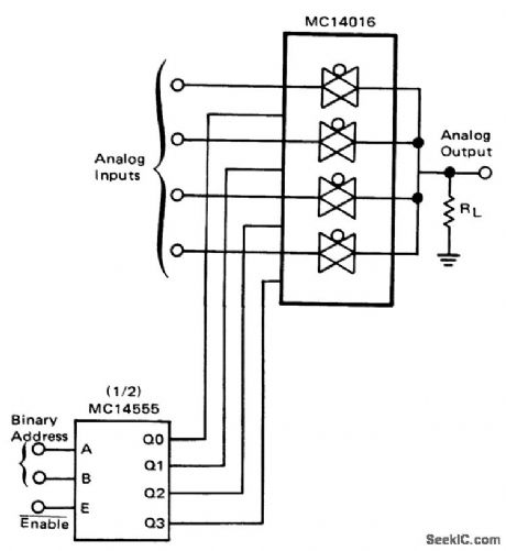
4-channel analog data selector (courtesy Motorola Semiconductor Products Inc.). (View)
View full Circuit Diagram | Comments | Reading(1372)
Capacitor_discharge_SCR_ignition_system
Published:2009/7/21 1:59:00 Author:Jessie
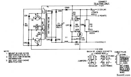
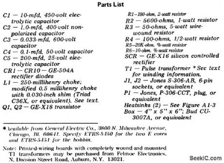
Capacitor discharge SCR ignition system. The circuit draws less than 1 ampere at high RPM (courtesy General Electric Company). (View)
View full Circuit Diagram | Comments | Reading(2588)
Push_pull_discrete_Darlington_amplifier
Published:2009/7/21 1:54:00 Author:Jessie
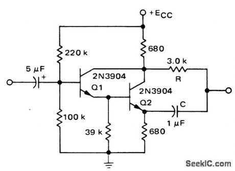
Push-pull discrete Darlington amplifier (courtesy Motorola Semiconductor Products Inc.). (View)
View full Circuit Diagram | Comments | Reading(3364)
Multiplier_with_discrete_level_shift
Published:2009/7/21 1:50:00 Author:Jessie
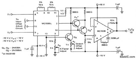
Multiplier with discrete level shift (courtesy Motorola Semiconductor Products Inc.). (View)
View full Circuit Diagram | Comments | Reading(775)
Multiplier_circuit_using_an_MC1595
Published:2009/7/21 1:47:00 Author:Jessie
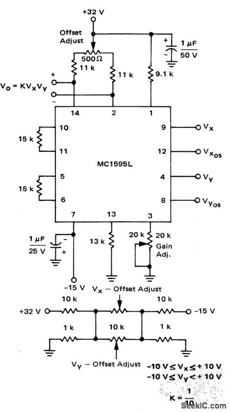
Multiplier circuit using an MC1595 (courtesy Motorola Semiconductor Products Inc.). (View)
View full Circuit Diagram | Comments | Reading(1231)
Divider_with_digitally_controlled_gain
Published:2009/7/21 2:31:00 Author:Jessie
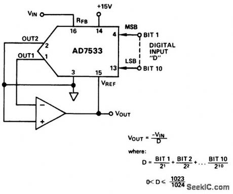
Divider with digitally controlled gain (courtesy Analog Devices, Inc.). (View)
View full Circuit Diagram | Comments | Reading(710)
Cold_junction_compensation_circuit_for_type_J_thermocouple
Published:2009/7/21 2:30:00 Author:Jessie
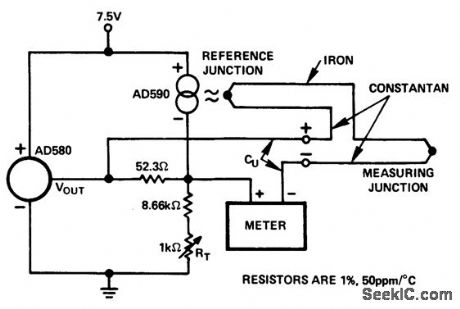
Cold junction compensation circuit for type J thermocouple(courtesy AnalogDevices,inc.). (View)
View full Circuit Diagram | Comments | Reading(1306)
One_quadrant_multiplication_using_a_DAC_IC10BC_D_A_converter_and_AM_452_op_amp
Published:2009/7/21 2:29:00 Author:Jessie
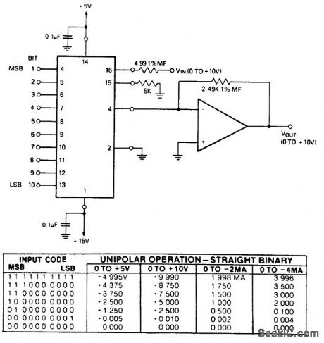
One-quadrant multiplication using a DAC-IC10BC D/A converter and AM-452 op amp. See coding table. With VIN connected to pin 16 the input impedance is low; with it connected to pin 15 the input impedance is high. The range is then 0 to -10 volts (courtesy Datel Systems, Inc.). (View)
View full Circuit Diagram | Comments | Reading(722)
General_purpose_amplifier_with_FET_AGO_circuit
Published:2009/7/21 2:27:00 Author:Jessie
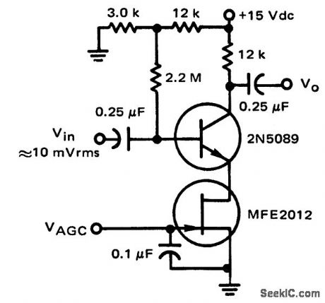
Voltage offset null circuit using an ECG915 operational amplifier. See basing diagram for supply connections. Supply is ±15 volts (courtesy GTE Sylvania Incorporated) (View)
View full Circuit Diagram | Comments | Reading(885)
Voltage_offset_null_circuit_using_an_ECG915_operational_amplifier
Published:2009/7/21 2:26:00 Author:Jessie
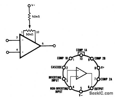
Voltage offset null circuit using an ECG915 operational amplifier. See basing diagram for supply connections. Supply is ±15 volts (courtesy GTE Sylvania Incorporated) (View)
View full Circuit Diagram | Comments | Reading(641)
Pulse_amplifier_using_an_MC1545G_for_applications_in_radar_IFs_pulse_width_modulation_and_pulse_amplitude_modulation_systems
Published:2009/7/21 2:20:00 Author:Jessie
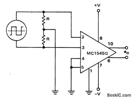
Pulse amplifier using an MC1545G for applications in radar IFs, pulse width modulation and pulse amplitude modulation systems (courtesy Motorola Semiconductor Products Inc.). (View)
View full Circuit Diagram | Comments | Reading(1725)
Voltage_controlled_amplifier_using_an_AD534_mulf_plier_divider_chip
Published:2009/7/21 2:39:00 Author:Jessie
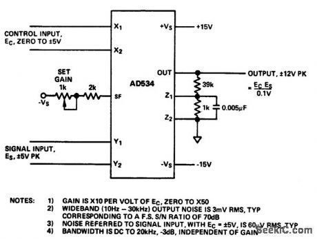
Voltage-controlled amplifier using an AD534 mulf plier/divider chip (courtesy Analog Devices, Inc.). (View)
View full Circuit Diagram | Comments | Reading(745)
1_watt_noninverting_power_amplifier_using_an_MC1554_connected_to_a_single_supply
Published:2009/7/21 2:37:00 Author:Jessie
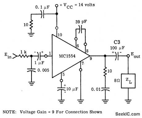
1-watt noninverting power amplifier using an MC1554 connected to a single supply. As shown voltage gain is nine (courtesy Motorola Semiconductor Products Inc.). (View)
View full Circuit Diagram | Comments | Reading(680)
Vector_computer_using_one_AD531_multiplier_divider_and_two_AD741_op_amps
Published:2009/7/21 2:32:00 Author:Jessie
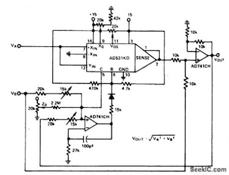
Vector computer using one AD531 multiplier/divider and two AD741 op amps. The circuit derives the square root of the sum of the squares (courtesy Analog Devices, Inc.). (View)
View full Circuit Diagram | Comments | Reading(1359)
Programmable_gain_noninverting_amplifier_with_selectable_inputs
Published:2009/7/21 2:31:00 Author:Jessie
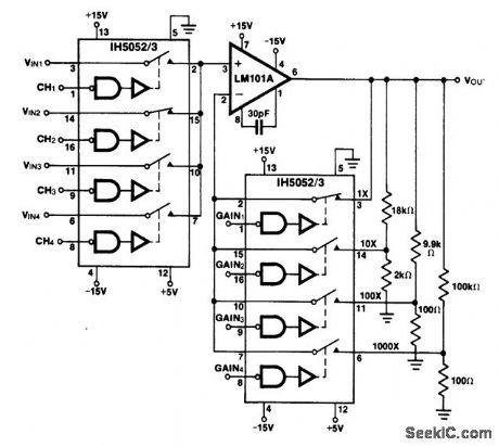
Programmable gain noninverting amplifier with selectable inputs. The IH5052/53 chips are 16-pin DIP CMOS analog gates (courtesy Intersil, Inc.). (View)
View full Circuit Diagram | Comments | Reading(732)
Power_generation_circuit_using_n_number_of_AD7524_8_bit_D_A_conveners
Published:2009/7/21 4:34:00 Author:Jessie
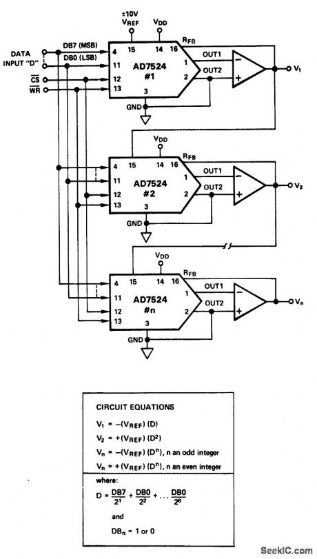
Power generation circuit using n number of AD7524 8-bit D/A conveners (courtesy Analog Devices, Inc.). (View)
View full Circuit Diagram | Comments | Reading(732)
CAMERA_CONTROL
Published:2009/7/21 4:33:00 Author:Jessie
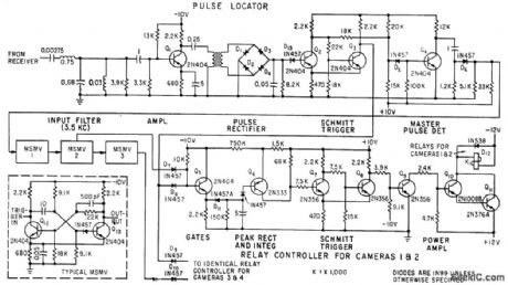
Circuit separates 3.5-kc pulses from other subcarrier signals at input filter, then amplifies, rectifies pulses, and squares pulses at Schmitt trigger. Four cameras can be controlled by system from single 460-Mc radio link.-F. M. Gardner and L. R. Hawn, Camera Control System for Rocket Sled Tests, Electronics, 33:14, p 63-65. (View)
View full Circuit Diagram | Comments | Reading(738)
Divider_circuit_using_an_AD533_multiplier_divider_chip
Published:2009/7/21 4:28:00 Author:Jessie
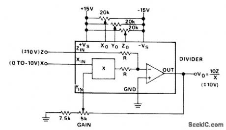
Divider circuit using an AD533 multiplier/divider chip. Set all pots at midrange. With Z equal to zero volts, trim Zo to hold the output constant as X is varied from -10 volts DO to - 1 volt DC. With Z equal to zero volts and X equal to - 10 volts DC trim Yo for zero volts DC. With Z equal to X or -X trim Xo for the minimum worst-case variations as X is varied from -10 volts DC to -1 volt DC. With Z equal to X or-X trim the gain for the closest average approach to ±10volts DC output as X is varied from -10 volts DC to -3 volts DC (courtesy Analog Devices, Inc.). (View)
View full Circuit Diagram | Comments | Reading(878)
Color_TV_video_IF_system
Published:2009/7/21 4:28:00 Author:Jessie
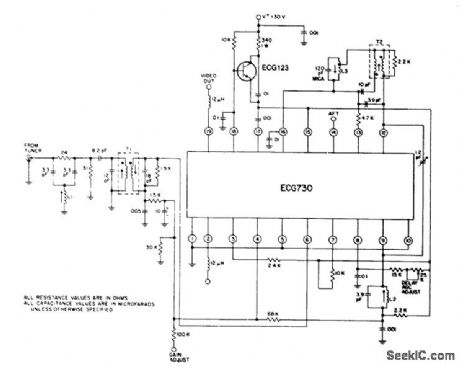
Color TV video IF system. Gain is typically 75 dB at 45 MHz tor the IF amplifier and 12 dB for the video amplifier. The chip contains a zener reference diode for convenient and economical power supply regulation (courtesy GTE Sylvania Incorporated). (View)
View full Circuit Diagram | Comments | Reading(738)
Video_signal_processor_for_eith_B﹠W_or_color_TV
Published:2009/7/21 4:24:00 Author:Jessie
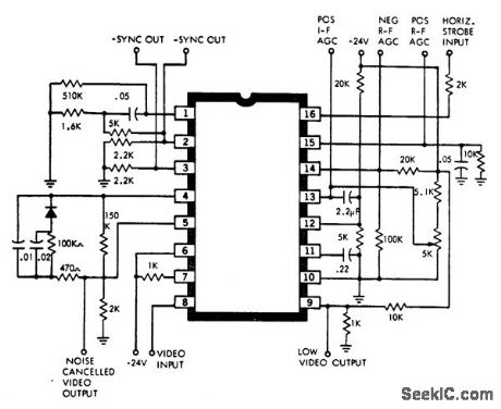
Video signal processor for eith B﹠W or color TV The chip contains a keyed AGC amplifier that provides forward AGC voltage for video IF amplifiers and tuners equipped with NPN bipolar transistors. It provides compdsite sync outputs with positive and negative going signals. There's also reverse AGC voltage for tuners equipped with MOSFETs, PNP bipolar transistors, or tubes in the BF stage. The video output is a low-impedance emitter follower. In addition there's a preset noise detector for gating the chip's sync separator and AGC detector (courtesy GTE Sylvania Incorporated). (View)
View full Circuit Diagram | Comments | Reading(957)
| Pages:34/126 At 202122232425262728293031323334353637383940Under 20 |
Circuit Categories
power supply circuit
Amplifier Circuit
Basic Circuit
LED and Light Circuit
Sensor Circuit
Signal Processing
Electrical Equipment Circuit
Control Circuit
Remote Control Circuit
A/D-D/A Converter Circuit
Audio Circuit
Measuring and Test Circuit
Communication Circuit
Computer-Related Circuit
555 Circuit
Automotive Circuit
Repairing Circuit