Electrical Equipment Circuit
Index 29
HEART_STIMULATING_PULSE_OUTPUT_STAGE
Published:2009/7/20 20:42:00 Author:Jessie

Used in conjunction with pulse amplifier to increase stimulating voltage when scar tissue develops under electrodes sewn to auricle and ventricle of heart, introducing excessive load resistance. Produces constant-voltage positive-going pulse having maxi-mum amplitude of 15 V and0.1-sec duration, when triggered by positive pulse.-G. F. Vanderschmidt, Two-Transistor Amplifier Corrects Heart Block, Electronics, 31:47, p 80-81. (View)
View full Circuit Diagram | Comments | Reading(911)
EEG_WAVEFORM_ANALYZER
Published:2009/7/20 20:40:00 Author:Jessie

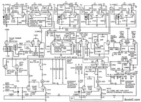
Uses derivative curves of primary eeg signals to quantitatively describe waveshape deviations of irregular electrical waveforms emitted by brain, in terms of time and amplitude. Oporates on zero-crossing detector measurements to produce analog voltages proportional to time between base periods and also proportional to time values of left and right deviation coefficients.-C. J. Zaander, Computer Ancalyzes Brain Waveforms, Electronics, 31:29, p 68-72. (View)
View full Circuit Diagram | Comments | Reading(2930)
Anbaolu microwave safe control board circuit diagram
Published:2011/8/2 2:23:00 Author:Rebekka | Keyword: Anbaolu, microwave safe control board

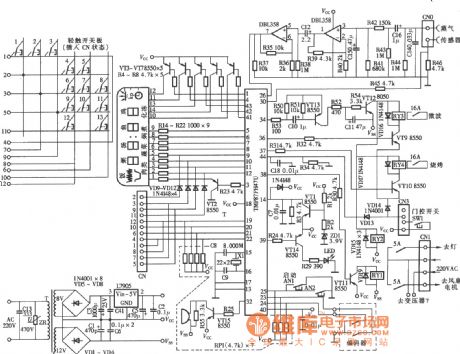
Here is the diagram of anpo road microwave safe control board circuit. (View)
View full Circuit Diagram | Comments | Reading(2151)
FOUR_RANGE_VTVM
Published:2009/7/20 23:31:00 Author:Jessie

Measures r-f power oscillator output, for establishing irradiation and calibration procedures and positioning techniques when using focused ultrasound for therapeutic treatment of deep-seated brain structures.-B. J. Cosman and T. F.Hueler, Instrumentation for Ultrasonic Neurosurgery, Electronics, 32:20, p 53-57. (View)
View full Circuit Diagram | Comments | Reading(988)
900_MHz_to_45_MHz_mixer_using_a_3N225_dual_gate_MOSFET
Published:2009/7/20 23:31:00 Author:Jessie

900 MHz to 45 MHz mixer using a 3N225 dual-gate MOSFET (courtesy Texas Instruments Incorporated). (View)
View full Circuit Diagram | Comments | Reading(713)
BATTERYLESS_CARDIAC_PACEMAKER
Published:2009/7/20 23:30:00 Author:Jessie

Body fluids are electrolyte for implanted silver and zinc electrodes that provide d-c power for four-transistor pacemaker. Secondary of T1 provides feedback for ringing-choke oscillator Q1, which charges C until Q2 is cut off. C then discharges until Q1 can again con duct.-O. Z. Roy and R. W. Wehnert, Keeping the Heart Alive with a Biological Battery, Electronics, 39:6, p 105-107. (View)
View full Circuit Diagram | Comments | Reading(2673)
3_MC_COLPITTS_FOR_TONOMETER
Published:2009/7/20 23:29:00 Author:Jessie


Frequency shift is proportional to pressure on quartz crystal-D. E. Newell, C. H. Horn, and M. L. Rubin, Measuring Eyeball Pressure with a Crystal Oscillator, Electronics, 34:36, p 64-65. (View)
View full Circuit Diagram | Comments | Reading(869)
PILL_TRACING_INTEGRATOR
Published:2009/7/20 23:28:00 Author:Jessie

Voltage proportional to speed of travel of pill-sized radio transmitter in human body is integrated in quantizing circuit that delivers number of pulses proportional to track length. Transistor differential amplifier charges C, and Schmitt trigger controls discharge of C through R2.Frequency of trigger pulses is proportional to input voltage within 1% over range of 2 to 200 mv,-B. Jacobson and B Lindberg, Servo Tracks Pill in Human Body,Electronics,36:12,p58-60. (View)
View full Circuit Diagram | Comments | Reading(1105)
SLIDING_GATE_FOR_HEART_SOUNDS
Published:2009/7/20 21:05:00 Author:Jessie

Two multivibrators, synchronized with time reference,permit listening to selected portions of heart sound. Potentiometers permit adjusting width and position of gate.-R. Weiss, Heart-Sound Discriminator Simplifies Medical Diagnosis, Electronics, 34;24, p 52-55. (View)
View full Circuit Diagram | Comments | Reading(876)
ARTIFICIAL_LARYNX
Published:2009/7/20 21:04:00 Author:Jessie

Output is negative pulse whose repetition frequency is varied from 100 to 200 cps by rheostat to change pitch of voice while speaking. Modified telephone receiver serves as vibrator that is pressed against throat to transform generated vibrations into speech sounds by normalmal use of throat cavity, tongue, mouth, teeth, and lips. With practice, users can achieve sentence intelligibility above 97%.-Circuit Substitutes as Larynx, Electronics, 32:27, p 60-63. (View)
View full Circuit Diagram | Comments | Reading(1511)
L_I_N_E_A_R_TRANSISTORIZED_HORIZONTAL_SWEEP
Published:2009/7/20 21:03:00 Author:Jessie

Placing transformer in yoke circuit provides better thon 0.5% linearity for deflecting 16.inch crt having 52° defection angle and 15-kv accelercation voltage. Line rate is 28.35 kc with 945 lines; Supply voltage determines width or amplitude of sweep. C can be increased to get 525-line rate.-J. W. Greininger, Improving Lineority in Transistorized Horizontal Sweeps, EEE, 12:9, p 61-62. (View)
View full Circuit Diagram | Comments | Reading(794)
PLETHYSMOGRAPH
Published:2009/7/20 20:57:00 Author:Jessie

Transistorized unit measures change in impedance of living tissue resulting from nonrythmic fluctuations of blood content Changes of 0.1% in total tissue impedance are detected by resistance bridge and phase-sensitive detector that scans bridge unbalance.-S. Bagno and F. M.Liebman, Impedance Measurements of Living Tissue, Electronics, 32:15, p 62-63. (View)
View full Circuit Diagram | Comments | Reading(2477)
CONDUCTIVITY_METER
Published:2009/7/20 20:57:00 Author:Jessie

Circuit using single quad opamp measures relative change in con-centration of salt solution by monitoring its conductance. Use of alternating current through solution eliminates errors caused by electrolysis effect. Wien-bridge oscillator having R4C1 and R4R3 as arms of bridge generates 1-kHz signal for driving amplifier A2 through solution. P1 controls oscillator amplitude, and P2 adjusts gain of A2. A3-A4 form precision rectifier giving output voltage equal to absolute value of input voltage.-M. Ahmon, One-Chip Conductivity Meter Monitors Salt Concentration, Electronics, Sept. 15, 1978, p 132-133. (View)
View full Circuit Diagram | Comments | Reading(0)
Percent_of_deviation_ratio_computer
Published:2009/7/21 2:09:00 Author:Jessie

Percent of deviation ratio computer (courtesy Analog Devices, Inc.). (View)
View full Circuit Diagram | Comments | Reading(618)
Fuda Brand ZL130-81 Dry And Wet Vacuum Cleaner Circuit
Published:2011/8/2 22:05:00 Author:Robert | Keyword: Fuda, Dry, Wet, Vacuum Cleaner

The picture shows the Fuda Brand ZL130-81 dry and wet vacuum cleaner circuit.
The XP is power plug. The S is power switch. The FU is fuse. The T is power transformer. The K1 is relay. The K1-1 is relay K1's normally openning contactor. The IC is integrated circuit. The VT is triode. The SP is air pressure sensor. The XT is terminal board. The M is motor. The VD1, VD2are indication lamps. (View)
View full Circuit Diagram | Comments | Reading(3001)
Latch_circuit_using_an_LM3909_chip
Published:2009/7/21 2:39:00 Author:Jessie

Latch circuit using an LM3909 chip. Circuitry inside dashed lines is the LM3909, The circuit switches to and holds its condition whenever the switch changes sides (courtesy National Semiconductor Corporation). (View)
View full Circuit Diagram | Comments | Reading(720)
Driving Circuit Transformer Primary And Secondary Circuit
Published:2011/8/3 10:18:00 Author:Robert | Keyword: Driving, Transformer, Primary, Scondary

The picture shows the IGBT switch tube's driving circuit transformer primary and secondary principle circuit. The R235-R238 are grid electrode series resistance. It is important for IGBT grid electrode driving by selecting adequate grid electrode series resistors.Its openning and closing are achieved by the grid electrode circuit's charging and discharging. The grid electrode resistor with low value would make the grid electrode capacitot's charging and discharging be fast. So it would reduce the switching time and switching power consumption. When it has short circuits or it is during the closing time of fly-wheel diode which has bridge connection to the crossing IGBT, the added du/dt on the IGBT and its collector polar's a grid electrode capacitor could cause the case that there is current through the grid electrode circuit. If this current is large enough, this would generate voltage between grid electrode resistors and make the IGBT be wrong connected. (View)
View full Circuit Diagram | Comments | Reading(785)
NEON_LAMP_OSCILLATOR
Published:2009/7/21 3:02:00 Author:Jessie

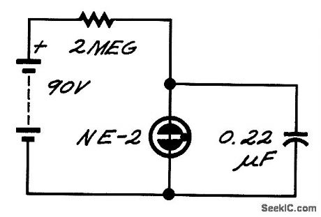
The neon lamp has negative dynamic resistance-the voltage across it falls while conduction is increasing. As a result, it flashes on and off.The frequency depends on the time constant RC and the supply voltage, as well as lamp characteristics. (View)
View full Circuit Diagram | Comments | Reading(1306)
Konka R878 mobile phone cable connection figure
Published:2011/8/3 1:21:00 Author:Ecco | Keyword: Konka , mobile phone , cable connection
View full Circuit Diagram | Comments | Reading(628)
Konka R878 mobile phone cable connection schematic diagram
Published:2011/8/3 1:24:00 Author:Ecco | Keyword: Konka , mobile phone , cable connection
View full Circuit Diagram | Comments | Reading(1260)
| Pages:29/126 At 202122232425262728293031323334353637383940Under 20 |
Circuit Categories
power supply circuit
Amplifier Circuit
Basic Circuit
LED and Light Circuit
Sensor Circuit
Signal Processing
Electrical Equipment Circuit
Control Circuit
Remote Control Circuit
A/D-D/A Converter Circuit
Audio Circuit
Measuring and Test Circuit
Communication Circuit
Computer-Related Circuit
555 Circuit
Automotive Circuit
Repairing Circuit

