
Index 47
Musical Bell with Touch Switch
Published:2013/3/25 3:43:00 Author:Ecco | Keyword: Musical Bell, Touch Switch
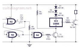
Here the circuit diagram of musical bell with touch switch and timer. This circuit is designed around CMOS IC CD4011 which work as the delay timer and IC UM66 which is well-known musical sound generator. When touch plates are bridged (touched) by hand for a moment, the circuit will start to produce music sound. Just after a short period (few seconds), the musical sound from this circuit will automatically stop.
(View)
View full Circuit Diagram | Comments | Reading(905)
Inversed monostable circuit
Published:2013/3/25 2:39:00 Author:Ecco | Keyword: Inversed monostable
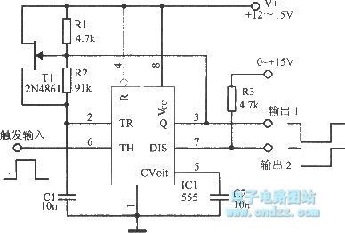
Inversed monostable circuit is shown as figure.
(View)
View full Circuit Diagram | Comments | Reading(560)
4 ~ 4.6MHz tuner
Published:2013/3/25 2:18:00 Author:Ecco | Keyword: 4 ~ 4.6MHz tuner
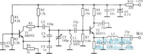
4 ~ 4.6MHz tuner is shown as figure.
(View)
View full Circuit Diagram | Comments | Reading(589)
MOS FET unsteady state circuit
Published:2013/3/25 2:15:00 Author:Ecco | Keyword: MOS FET, unsteady state

MOS FET unsteady state circuit is shown as figure.
(View)
View full Circuit Diagram | Comments | Reading(601)
Pulse triggering monostable circuit
Published:2013/3/14 1:49:00 Author:Ecco | Keyword: Pulse triggering, monostable

Pulse triggering monostable circuit is shown as figure.
(View)
View full Circuit Diagram | Comments | Reading(650)
Bidirectional monostable circuit
Published:2013/3/14 1:40:00 Author:Ecco | Keyword: Bidirectional monostable

Bidirectional monostable circuit is shown as figure.
(View)
View full Circuit Diagram | Comments | Reading(589)
The PC Serial Port Receiver circuit
Published:2013/3/10 23:08:00 Author:Ecco | Keyword: PC Serial Port , Receiver

This circuit requires physical connections be made to the computer's serial port (COM1 or 2). To the best of my knowledge, it is difficult to cause damage to yourself or your computer by improper connections to this port, but there is no guarantee that damage will not result. Use caution when making any external electrical connections.
(View)
View full Circuit Diagram | Comments | Reading(1750)
Lightning Activated Camera Shutter Trigger
Published:2013/3/10 23:03:00 Author:Ecco | Keyword: Lightning Activated Camera, Shutter Trigger

In a nutshell, the photo darlington converts light pulses into electrical pulses, the first LM324 section amplifies the electrical pulses, the second LM324 section is a high pass filter that only passes quick changes (lightning). The third LM324 stage is a comparator that allows only large pulses to pass through, and the 4047 one-shot stretches out the length of the pulses so that they are long enough to drive the relay and trigger the camera.
The 2N3904 drives the reed relay, which in turn triggers the camera's electronic shutter switch. The VN10KM prevents the circuit from triggering the camera when it is first turned on. The LM324 GND Ref circuit divides the 9V power into two for a 4.5V ground reference. The other op-amp circuits use this reference value.
(View)
View full Circuit Diagram | Comments | Reading(989)
Motorized Video Camera Mount
Published:2013/3/10 22:53:00 Author:Ecco | Keyword: Motorized, Video Camera , Mount

The camera rotator circuit uses a 2716 EPROM to store a table of logic values that control the motor driver (H-bridge) circuit. The EPROM data is shown in the schematic. By using the EPROM, a large number of discrete gates are eliminated. The logic table is designed to allow the motor to turn clockwise until the clockwise limit sensor is activated. The same operation happens with counter clockwise rotation and the counter clockwise limit sensor.
Four bits of input come from the limit sensors and the direction control switch, these go to the EPROM address lines. All of the input signals are low-active. Four EPROM outputs go to the four H-bridge transistor gates. The control switch signals are buffered through the 7400 quad NAND gate, this allows for a long control wire. The control wire should be a shielded type such as beldfoil and the shield should be grounded at only one side.
The H-bridge array consists of two N-channel MOSFETs and two P-channel MOSFETs. Diagonal pairs of transistors are turned on to move the motor one way or the other. If all of the transistors are off, the motor does not move. Note that the P channel transistors turn on with a 0 logic output level and the N channel transistors turn on with a 1 logic output level.
There are several disallowed output states, if the wrong two transistors are turned on, the transistors and voltage regulator would heat up and possibly be destroyed. Don't do this. If the EPROM is programmed correctly, this should never happen.
(View)
View full Circuit Diagram | Comments | Reading(2104)
CDV700 Geiger Counter Probe Rebuilding
Published:2013/3/10 22:50:00 Author:Ecco | Keyword: Geiger Counter, Probe Rebuilding

This article describes the process of rebuilding a geiger counter probe from the Victoreen CDV700 geiger counter. The process of converting the hard-wired probe to a probe with a pluggable BNC connector is also described. The probe from the model CDV700-6B is similar, but not identical, the socket is easier to access on that model.
(View)
View full Circuit Diagram | Comments | Reading(762)
Count Accumulator for Radiation Levels (CARL)
Published:2013/3/10 22:49:00 Author:Ecco | Keyword: Count Accumulator, Radiation Levels , CARL
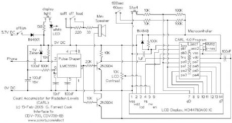
The CARL device is an add-on numerical counter that plugs into the headphone jack of 1960s vintage geiger counters such as the Victoreen CDV700 and CDV700-6B. It should also work with the Lionel ENI/LENi counters, and any other geiger counter that has a headphone output pulse greater than -5V.
Vintage 1960s era geiger counters don't actually count, they use an analog meter with an integrator circuit to give short-term averaged readings of radiation detections (clicks). The CARL circuit keeps track of the total number of clicks for a period of either 60 or 600 seconds (1 or 10 minutes). This provides a way to get a long-running count of low-level radiation from sources such as radon gas, rock samples and background radiation. The CARL circuit allows for the measurement and comparison of radioactive sources that are of levels that don't produce measurable readings on analog geiger counter meters.
In my Colorado location, the CARL counter shows background radiation levels of 15-20 clicks per minute upstairs and 20-25 clicks per minute in basements where radon gas is present.
As a collector of rocks, my interest in making this device was to find all of the radioactive minerals in my collection, and remove them from my living space. I found quite a few rocks that registered above the background level, fortunately, I did not find anything super-hot. I have also used the meter to compare background levels in various geographical locations.
(View)
View full Circuit Diagram | Comments | Reading(1154)
Hot Rodding a CDV700 Geiger Counter
Published:2013/3/10 22:47:00 Author:Ecco | Keyword: Hot Rodding, Geiger Counter
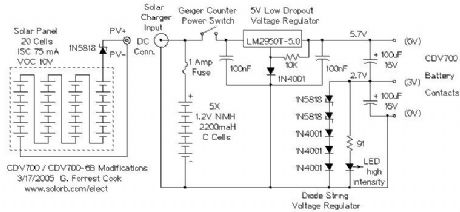
The original power supply for the CDV700 and CDV700-6B uses two pairs of D cell batteries. The 3V-6V battery set supplies the oscillator circuit with 33ma of current when properly adjusted. The 0V-3V battery set supplies the detector circuit with a few ma of current. This causes the batteries to wear out at different rates.
Conversion to modern NiMH C cells allows the counter to run for longer periods of time. The rechargeable batteries work well with a small solar panel for recharging. A set of 5 AA-size NiMH cells would also work for this application. NiCd cells can also be used, but NiMH cells have higher power density and are generally better batteries.
After six years of occasional use, both of these meters are still running fine on the original NiMH battery sets. The PV panels have been located indoors on sunny window sills.
(View)
View full Circuit Diagram | Comments | Reading(669)
TTL Pulse Reading Logic Probe
Published:2013/3/10 22:46:00 Author:Ecco | Keyword: TTL Pulse, Reading , Logic Probe

This circuit can be built on perforated circuit board and wired by hand. The completed circuit can be assembled into a clear plastic box with the wires protruding out one end. The LEDs should be visible through the box. IC sockets should be used for easy chip replacement.
(View)
View full Circuit Diagram | Comments | Reading(886)
Octopus Curve Tracer
Published:2013/3/10 22:45:00 Author:Ecco | Keyword: Octopus Curve Tracer

This project involves the construction of a low-cost curve tracer that is suitable for testing a wide variety of electronic components both in-circuit and out of circuit. It is easy to construct and extremely useful for finding defective parts, especially semiconductors, in electronic devices.
The octopus is used in conjuction with an oscilloscope set to display in X-Y mode. It displays voltage across the test probes on one axis and current through the probes on the other axis. A scope with both Horizontal and Vertical inputs (X-Y mode) is required.
This is my version of a circuit that has been around since at least the 1960s, I added the ability to select voltage taps on the filament transformer and adjust the amount of current through the probes.
(View)
View full Circuit Diagram | Comments | Reading(4968)
Frequency Calibrator for AM and Shortwave Radios
Published:2013/3/10 22:42:00 Author:Ecco | Keyword: Frequency Calibrator , AM , Shortwave Radios

The circuit was built on a hand-wired prototype board as shown in the photo, a more permanent circuit could be built with a OnePas prototype board or a hand-wired perf-board. IC sockets are recommended for more permanent wiring jobs. Selection of the available frequencies can be done with an optional 1P5T rotary switch or a board-mounted 5 position DIP switch. In the prototype shown, frequency selection is done by moving a jumper wire.
The 5VDC supply is provided by an external DC power supply, four 1.25 NiMH cells could also be used. If you use NiMH cells, don't forget to add a fuse and a switch. It is a good idea to build the circuit into a small metal box, use insulated standoffs and machine screws to mount the board to the box.
(View)
View full Circuit Diagram | Comments | Reading(926)
PC Automatic Power-on Circuit
Published:2013/3/10 22:38:00 Author:Ecco | Keyword: PC Automatic, Power-on Circuit

This project is for a power-on boot sequencer that works with PC-style computers that have a low-voltage controlled power supply such as an ATX or Mini-ITX system. Some computers have built-in BIOS functionality that can be set to boot up the computer when AC power is applied, others do not. This circuit is intended for the latter type of computer.
A desktop PC can be used for a variety of dedicated purposes such as a home automation controller, a burglar alarm or an automatic motion-operated camera. Such a system needs to be able to automatically restart when the AC mains power drops out and comes back on. A battery-backed uninterruptible power supply (UPS) is normally a good solution for this problem, but if the power remains off for long enough, the UPS battery will drain and the computer will eventually power down.
This circuit can be used to manage computers that are located in remote locations. It is also useful for booting normal desktop systems where the power to the CPU, monitor and printer are controlled from a single plug-strip.
This circuit provides the necessary timing to virtually press the PC's power on switch and the PC's reset switch. If the PC uses an external 12V power supply, such as a Mini-ITX device, power for this circuit can come from the PC's power supply. For larger desktop systems, it may be necessary to power this circuit with an external 12V DC supply such as a wall-wart.
(View)
View full Circuit Diagram | Comments | Reading(1241)
Microprocessor RS-232 Reset
Published:2013/3/10 22:36:00 Author:Ecco | Keyword: Microprocessor, Reset

This circuit allows a remote microprocessor to be reset by a controlling host by sending a break signal over an RS-232 or RS-422 serial line. If the remote machine resets into a simple program loader program, it is possible for the host to halt and restart, or halt and reload/restart the remote machine's program. This is an ideal way to develop software on older EPROM-based systems. Modern EEPROM/NVRAM systems use JTAG interfaces for similar results.
The remote processor runs its target code out of RAM, allowing the code to be updated easily. The circuit is usually used for developing code on a target processor, but it can also be used for permanent applications where the target program lives on a host system's disk. This system was once used to load code into a microprocessor-based satellite receiving system in Hawaii from a host system in Colorado using an Internet-based remote serial communications program.
(View)
View full Circuit Diagram | Comments | Reading(640)
Isolated Telephone Interface
Published:2013/3/10 22:27:00 Author:Ecco | Keyword: Isolated Telephone Interface

This circuit allows you to record audio from a telephone line into a tape recorder or computer soundcard without any hum. Most of the parts for this circuit can be scrounged from an old modem. With some rewiring work, it should possible to build this project into the old modem's case and re-use the built-in phone connectors.
Note that some countries have laws that require the user of a phone recording device to notify the party on the other end of the line that they are being recorded.
(View)
View full Circuit Diagram | Comments | Reading(1203)
Arduino LFO Waveform Generator V1
Published:2013/3/10 22:18:00 Author:Ecco | Keyword: Arduino, LFO Waveform , Generator, V1

This project uses an Arduino microprocessor and a DAC0808 8 bit parallel DAC to produce arbitrary low frequency oscillator (LFO) waveforms. These waveforms are useful for driving a tremolo/vibrato circuit in a guitar amplifier such as the Lil Tiger or a phaser effect such as the Liquidator. The second version of this project improves on this design by using a serial DAC chip and an analog speed control.
The initial version of this project was build using the Arduino Diecimila development board and an Arduino prototype shield for the DAC and associated parts. The original assembly can be seen in the photographs of the Lil Tiger project. The second generation version (as shown in the schematic) was built using just the Arduino's Atmega 126 processor chip on a stand-alone circuit board. The microprocessor should be programmed on the Arduino board then moved to the standalone LFO board. The circuit is a descendent of my older waveform generator project.
(View)
View full Circuit Diagram | Comments | Reading(7648)
Panner Waveform Generator
Published:2013/3/10 22:16:00 Author:Ecco | Keyword: Panner Waveform Generator

This device is a microprocessor controlled waveform generator that can be used for driving a voltage controlled stereo panner for music applications. Panning is simply the movement of a mono audio signal between the left and right channels of a stereo sound system.
The circuit can also be used to drive other voltage controlled modules that are used in analog music synthesis. The output of the waveform generator is a 0-10V DC control voltage.
One of eight waveforms can be selected using an 8 position BCD switch. Waves include: ramp, triangle, sine, cos(x)*sin(5x), damped 4 cycle sine wave, and pseudo random. Other waveforms may be substituted by changing the assembly language waveform tables.
The waveform generator runs in an asyncronous manner, int can be syncronized with other devices by use of an external (5V logic) sync signal or a manual sync trigger button. The waveform is generator is clocked by an oscillator circuit, the oscillator has three range selections, and an LFO rate control for fine speed adjustments.
The output waveform can be smoothed with an adjustable low pass filter. This can be used to remove the stair steps in the output waveform for a more rounded waveform.
An array of 8 LEDs is included for displaying where the current panning position is located, these are spread evenly across the device front panel for an interesting visual effect.
(View)
View full Circuit Diagram | Comments | Reading(788)
| Pages:47/471 At 204142434445464748495051525354555657585960Under 20 |
Circuit Categories
power supply circuit
Amplifier Circuit
Basic Circuit
LED and Light Circuit
Sensor Circuit
Signal Processing
Electrical Equipment Circuit
Control Circuit
Remote Control Circuit
A/D-D/A Converter Circuit
Audio Circuit
Measuring and Test Circuit
Communication Circuit
Computer-Related Circuit
555 Circuit
Automotive Circuit
Repairing Circuit