
Index 54
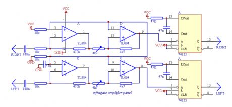
Infrared gate 3
Published:2013/2/18 21:12:00 Author:muriel | Keyword: Infrared gate
View full Circuit Diagram | Comments | Reading(562)
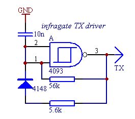
Infrared gate 2
Published:2013/2/18 21:12:00 Author:muriel | Keyword: Infrared gate
View full Circuit Diagram | Comments | Reading(549)
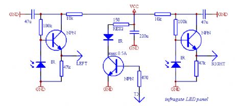
Infrared gate 1
Published:2013/2/18 21:12:00 Author:muriel | Keyword: Infrared gate
View full Circuit Diagram | Comments | Reading(573)
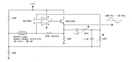
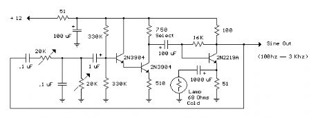
Low Frequency Wien Bridge RC Sinewave Oscillator 3
Published:2013/2/18 20:57:00 Author:muriel | Keyword: Low Frequency, Wien Bridge , RC Sinewave, Oscillator
View full Circuit Diagram | Comments | Reading(730)
Low Frequency Wien Bridge RC Sinewave Oscillator 2
Published:2013/2/18 20:57:00 Author:muriel | Keyword: Low Frequency, Wien Bridge , RC Sinewave , Oscillator
View full Circuit Diagram | Comments | Reading(583)
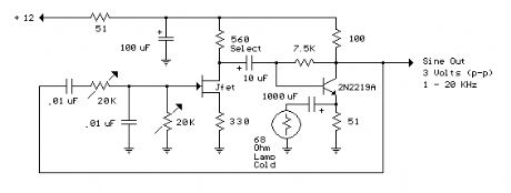
Low Frequency Wien Bridge RC Sinewave Oscillator 1
Published:2013/2/18 20:56:00 Author:muriel | Keyword: Low Frequency , Wien Bridge , RC Sinewave , Oscillator
View full Circuit Diagram | Comments | Reading(593)
Photodiode signal conditioning circuit diagram of barcode scanner
Published:2013/2/18 0:46:00 Author:Ecco | Keyword: Photodiode signal conditioning , barcode scanner
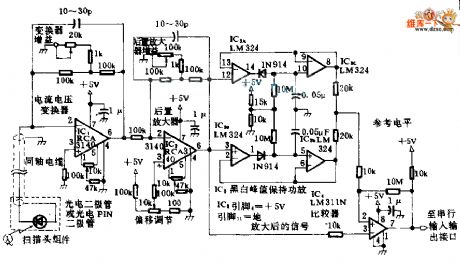
The circuit is used for processing the level signal of the photodiode in barcode scanner, the current output of IC1 will be converted into a voltage output and further being amplified in the IC2. The amplified signal is sent to the peak holding circuit, thereby establishing a reference level, then the comparator output is 0 or 1.
(View)
View full Circuit Diagram | Comments | Reading(1923)
Band pass filter diagran with operational amplifier
Published:2013/2/18 0:06:00 Author:Ecco | Keyword: Band pass filter, operational amplifier

Band pass filter diagran with operational amplifier is shown as figure.
(View)
View full Circuit Diagram | Comments | Reading(1188)
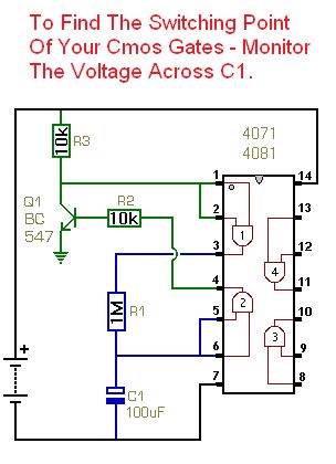
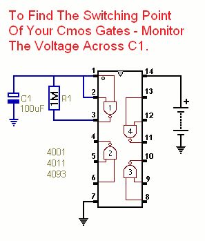
Circuit No.2 - Non-Inverters
Published:2013/2/17 20:09:00 Author:muriel | Keyword: Non-Inverters
View full Circuit Diagram | Comments | Reading(561)
Circuit No.1 - Inverters
Published:2013/2/17 20:09:00 Author:muriel | Keyword: Inverters
View full Circuit Diagram | Comments | Reading(454)
PNP transistor
Published:2013/2/17 20:02:00 Author:muriel | Keyword: PNP transistor

View full Circuit Diagram | Comments | Reading(1558)
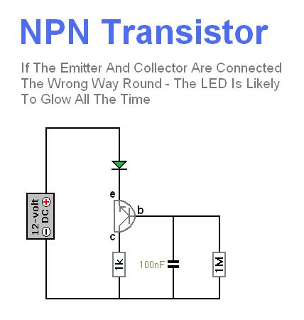
NPN transistor
Published:2013/2/17 20:02:00 Author:muriel | Keyword: NPN transistor
View full Circuit Diagram | Comments | Reading(1129)
Relay Pin Configuration
Published:2013/2/17 20:01:00 Author:muriel | Keyword: Relay


Relays are very versatile - but they're not magic. All they do is make and break sets of mechanical contacts. With careful observation - and a little logical thought - you can work out exactly what's happening inside the case.Start by finding the two pins connected to the relay coil. You can do this with your multimeter. The coil pins will be the only pair that exhibit a resistance. It's likely to be somewhere between about 50Ω and 1000Ω.Low voltage DC relay coils obeys Ohm's Law. That is: - Current = Voltage � Resistance. For example - the standard version of the 12v Omron G2E relay - has a coil resistance of 330Ω. So the current through the coil is 12v � 330Ω = 36mA. Always check for any markings that indicate coil polarity. Relay coils give off high reverse-voltage spikes that will destroy sensitive electronic components. These spikes are generated by the coil - when the relay de-energizes - and the coil's magnetic field collapses. They are generally removed by fitting an external suppressor diode - across the relay coil. See diode D1 on this Repeat Timer Schematic. However - Very Rarely - you'll find a relay that's fitted with an internal suppressor diode. If there is an internal suppressor diode - it's important that the coil is connected the right way round. Otherwise the diode will cause a short circuit. So - always check for polarity markings - just in case.You'll probably find that most relays will work satisfactorily with a range of supply voltages. For example - the standard 12v G2E will work from about 8 Volts - up to about 14 Volts. If you have no idea what voltage your coil is - start with say 3 volts - and increase it until the relay energizes. Next - switch the power off - and turn your attention to the remaining pins. With your meter - you should be able to divide them into two groups. Some pins will be joined together in pairs. And some pins will stand alone - with no connection to any other pin. Take a careful note of each.Although there will be exceptions - the stand alone pins are likely to be normally-open contacts. And the pairs of pins are most likely to be the pole and normally-closed contacts. Start with a normally-closed pair. One will be the pole - and the other will be the normally-closed contact. When power is applied to the coil - the pole will part from the normally-closed contact - and establish a new connection with the normally-open contact. When you switch off the power, the pole should part from the normally-open contact - and return to the normally-closed contact. (View)
View full Circuit Diagram | Comments | Reading(3643)
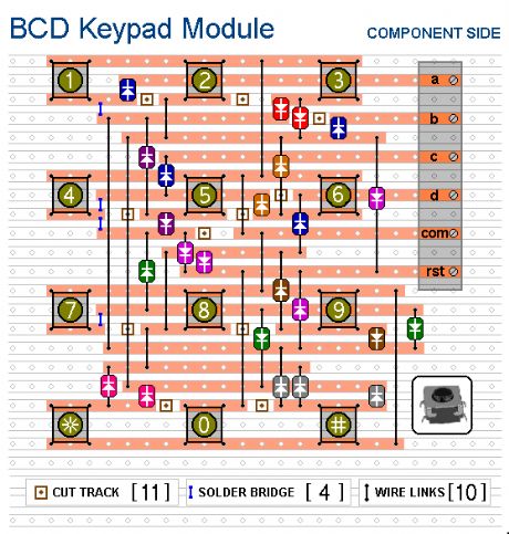
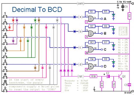
Decimal to BCD Decoder 2
Published:2013/2/17 19:58:00 Author:muriel | Keyword: Decimal to BCD Decoder
View full Circuit Diagram | Comments | Reading(639)
Decimal to BCD Decoder
Published:2013/2/17 19:57:00 Author:muriel | Keyword: Decimal to BCD Decoder
View full Circuit Diagram | Comments | Reading(1374)
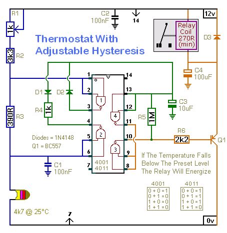
Thermostat With Adjustable Hysteresis
Published:2013/2/17 1:12:00 Author:muriel | Keyword: Thermostat, Adjustable Hysteresis
View full Circuit Diagram | Comments | Reading(1339)
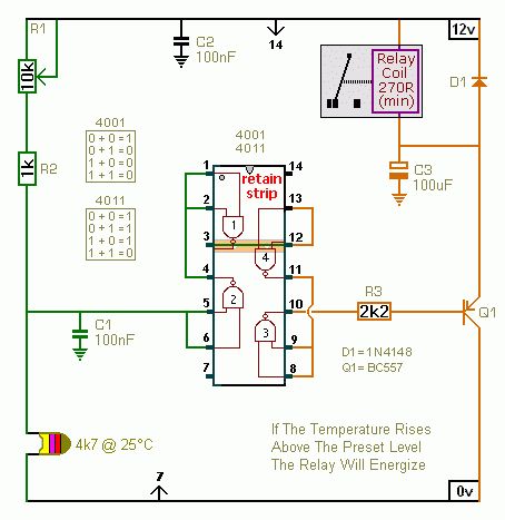
Two Temperature-Controlled Relays NO.2
Published:2013/2/17 1:11:00 Author:muriel | Keyword: Temperature-Controlled Relays

View full Circuit Diagram | Comments | Reading(539)
Two Temperature-Controlled Relays NO.1
Published:2013/2/17 1:11:00 Author:muriel | Keyword: Temperature-Controlled Relays
View full Circuit Diagram | Comments | Reading(557)
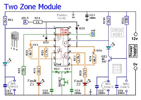
Two-Zone Expansion Module
Published:2013/2/1 20:12:00 Author:muriel | Keyword: Two-Zone , Expansion Module
View full Circuit Diagram | Comments | Reading(706)
Easy-Server V0.9
Published:2013/1/31 19:54:00 Author:muriel | Keyword: Easy-Server, V0.9
View full Circuit Diagram | Comments | Reading(723)
| Pages:54/471 At 204142434445464748495051525354555657585960Under 20 |
Circuit Categories
power supply circuit
Amplifier Circuit
Basic Circuit
LED and Light Circuit
Sensor Circuit
Signal Processing
Electrical Equipment Circuit
Control Circuit
Remote Control Circuit
A/D-D/A Converter Circuit
Audio Circuit
Measuring and Test Circuit
Communication Circuit
Computer-Related Circuit
555 Circuit
Automotive Circuit
Repairing Circuit