
Index 43
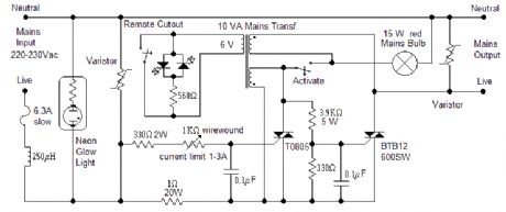
Electronic Fuse 2
Published:2013/5/7 21:10:00 Author:muriel | Keyword: Electronic Fuse

View full Circuit Diagram | Comments | Reading(935)
PULSE RELAY
Published:2013/5/7 21:09:00 Author:muriel | Keyword: PULSE RELAY
View full Circuit Diagram | Comments | Reading(742)
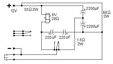
ELECTRONIC FUSE
Published:2013/5/7 21:08:00 Author:muriel | Keyword: ELECTRONIC FUSE
View full Circuit Diagram | Comments | Reading(0)
Electronic fish lure
Published:2013/5/7 21:07:00 Author:muriel | Keyword: Electronic fish lure

View full Circuit Diagram | Comments | Reading(2028)
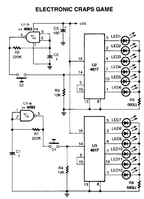
Electronic dice
Published:2013/5/7 21:07:00 Author:muriel | Keyword: Electronic dice
View full Circuit Diagram | Comments | Reading(0)
Electronic coin tosser
Published:2013/5/7 21:06:00 Author:muriel | Keyword: Electronic coin tosser

View full Circuit Diagram | Comments | Reading(539)
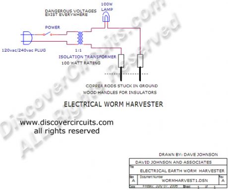
Electrical Device Harvests Earthworms 2
Published:2013/5/7 21:04:00 Author:muriel | Keyword: Electrical Device , Harvests Earthworms
View full Circuit Diagram | Comments | Reading(715)
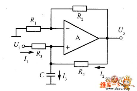
The improved differential circuit diagram
Published:2013/4/11 1:45:00 Author:Ecco | Keyword: improved differential
The improved differential circuit diagram is shown as figure.
(View)
View full Circuit Diagram | Comments | Reading(805)
INA101M basic application circuit diagram
Published:2013/4/11 1:46:00 Author:Ecco | Keyword: basic application
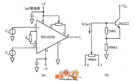
INA101M basic application circuit diagram is shown as figure.
(View)
View full Circuit Diagram | Comments | Reading(680)
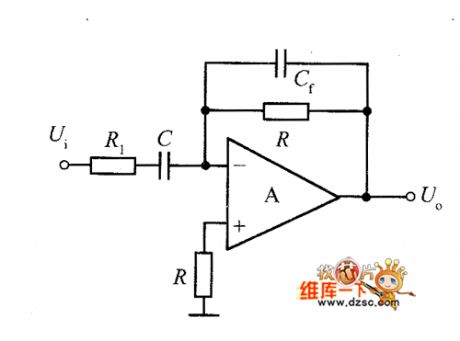
Basic same-phase integrator circuit
Published:2013/4/11 1:38:00 Author:Ecco | Keyword: Basic same-phase integrator
Basic same-phase integrator circuit is shown as figure.
(View)
View full Circuit Diagram | Comments | Reading(771)
Differential differential circuit diagram
Published:2013/4/11 1:36:00 Author:Ecco | Keyword: Differential differential

Differential differential circuit diagram is shown as figure.
(View)
View full Circuit Diagram | Comments | Reading(671)
Emitter-coupled bistable amplitude discriminating circuit
Published:2013/4/3 3:45:00 Author:Ecco | Keyword: Emitter-coupled, bistable amplitude, discriminating
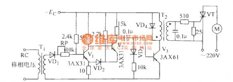
Emitter-coupled bistable amplitude discriminating circuit is shown as figure.
(View)
View full Circuit Diagram | Comments | Reading(689)
Fet Audio Mixer electronic circuit
Published:2013/4/1 3:15:00 Author:Ecco | Keyword: Fet Audio Mixer
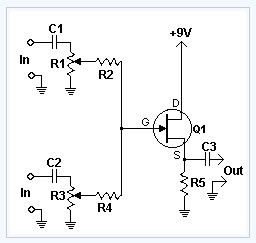
This simple circuit mixes two or more channels into one channel (eg. stereo into mono). The circuit can mix as many or as few channels as you like and consumes very little power. The mixer is shown with two inputs, but you can add as many as you want by just duplicating the sections which are clearly visible on the schematic.
(View)
View full Circuit Diagram | Comments | Reading(1125)
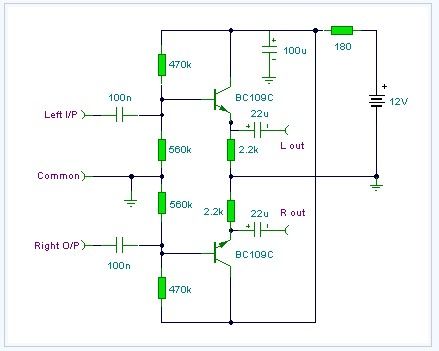
Audio Line Driver electronic circuit diagram
Published:2013/4/1 3:07:00 Author:Ecco | Keyword: Audio Line Driver
View full Circuit Diagram | Comments | Reading(1115)
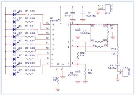
Audio Vu Meter 9 Leds electronic circuit diagram
Published:2013/4/1 3:04:00 Author:Ecco | Keyword: Audio, Vu Meter 9 Leds
View full Circuit Diagram | Comments | Reading(980)
3 Line Mixer electronic circuit
Published:2013/4/1 2:47:00 Author:Ecco | Keyword: 3 Line Mixer
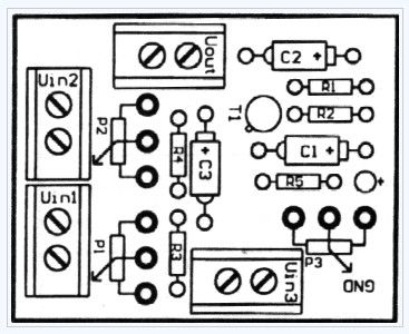
This project is a 3 or more lines mixer. For more than 3 inputs you can repeat the input parts (P=10K R=22K). It powered with 9Vdc.
(View)
View full Circuit Diagram | Comments | Reading(513)
Monitoring Off-Air Condition
Published:2013/3/29 4:43:00 Author:Ecco | Keyword: Monitoring Off-Air Condition
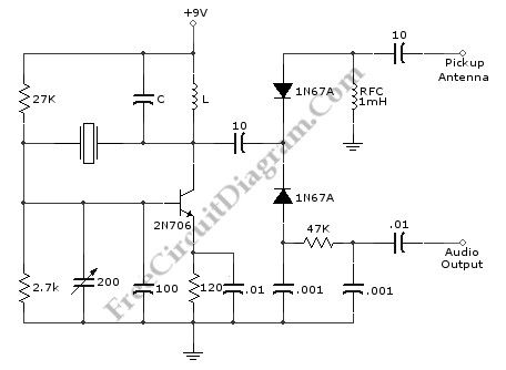
The circuit of off-air monitor for SSB transmitter can be built by using combination of detector product with the crystal oscillator. This circuit is used for testing the audio at one point within band. The quality of audio will still constant, if loading and tuning of SSB transmitter are same over rest of band. The LC circuit will resonated to band being used. When the transceiver is in receive mode, this circuit will spot the oscillator signal. And if the transceiver transmit the signal, the transceiver can be monitored. Here is the schematic diagram of the circuit:
(View)
View full Circuit Diagram | Comments | Reading(656)
Chromel Alumel Thermocouple Current Loop Transmitter circuit
Published:2013/3/29 4:41:00 Author:Ecco | Keyword: Chromel Alumel, Thermocouple Current Loop , transmitter

The schematic diagram below show signal conditioning circuit for remote current loop temperature transmitter. This thermocouple temperature transmitter is loop powered, means it doesn’t need its own power supply since the supply is provided by the current loop receiver. Thermocouple is basically a junction of two different metallic material that measures the temperature difference.
(View)
View full Circuit Diagram | Comments | Reading(1759)
Active Antenna With Gain (Booster) circuit
Published:2013/3/29 4:34:00 Author:Ecco | Keyword: Active Antenna , Gain (Booster)

This is an active antenna circuit with gain. This circuit is used to bost the signal. This circuit is made from a few transistors and other components. This circuit can provide RF gain of about12 to 18 dB. This circuit uses Q2 as a voltage amplifier. the RF signal direct-coupled from Q1’s Source terminal to the base of Q2. The Q3 is configured as an emitter-fallower amplifier which match and isolate the gam stage from the receiver’s RF-inputcircuitry. Here is the schematic diagram of the circuit:
(View)
View full Circuit Diagram | Comments | Reading(1745)
Transceiver Saver (Overvoltage Protector) circuit
Published:2013/3/29 4:33:00 Author:Ecco | Keyword: Transceiver Saver, Overvoltage Protector
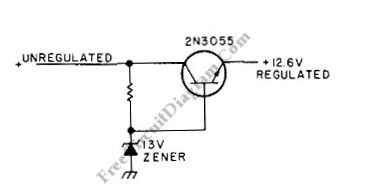
This is a transceiver saver circuit that protect a transceiver device (applicable to other device as well) from overvoltage of the power supply. This circuit is used to protect the device by regulating the power supply, avoiding damaging the device if overvoltage occurs. If the transceiver transmits current of above 2A, a heatsink should be used for the transistor. The value of resistor must provide output of 12.6 V during normal operation, you can make trial and error through measurement when choosing this., you can start with value around 100R. It’s recommended to use a high wattage Zener diode. Here is the schematic diagram of the circuit:
(View)
View full Circuit Diagram | Comments | Reading(603)
| Pages:43/471 At 204142434445464748495051525354555657585960Under 20 |
Circuit Categories
power supply circuit
Amplifier Circuit
Basic Circuit
LED and Light Circuit
Sensor Circuit
Signal Processing
Electrical Equipment Circuit
Control Circuit
Remote Control Circuit
A/D-D/A Converter Circuit
Audio Circuit
Measuring and Test Circuit
Communication Circuit
Computer-Related Circuit
555 Circuit
Automotive Circuit
Repairing Circuit