
Index 45
Axe Grinder Electric Guitar Effect
Published:2013/3/27 3:58:00 Author:Ecco | Keyword: Axe Grinder , Electric Guitar Effect

Here the schematic diagram of Axe Grinder Electric Guitar Effect. You may download the PDF version at the end of the post. The Axe Grinder is designed with a few key fetures in mind, it not only serves a wide range of distortion sounds clipping part of the effect, it also gives the user the ability to overload their amp with a greatly boosted clean tone.
(View)
View full Circuit Diagram | Comments | Reading(1042)
Dynamic Mic Compressor
Published:2013/3/27 3:57:00 Author:Ecco | Keyword: Dynamic Mic Compressor

The circuit below is a Dynamic Mic Compressor circuit is simple but the results are quite satisfactory. Audio output sounded outstanding. The principle of this circuit is very simple, the first transistor is used as Mic Pre-Amp. Then a second transistor used as a buffer. And the third transistor is a feedback circuit.
(View)
View full Circuit Diagram | Comments | Reading(1270)
Fender Bassman 5F6-A
Published:2013/3/27 3:57:00 Author:Ecco | Keyword: Fender Bassman

Here the schematic diagram of Fender Bassman 5F6-A amplifier. This circuit is a tube powered amplifier which is used as a bass guitar amplifier. Fender Bassman was a bass amplifier introduced by Fender in 1952. Although it was originally designed for bass guitars, it is often used for normal electric guitar in rock and roll, blues and country music.
(View)
View full Circuit Diagram | Comments | Reading(1123)
Dan Amstrong Blue Clipper Guitar Effect
Published:2013/3/27 3:56:00 Author:Ecco | Keyword: Dan Amstrong, Blue Clipper Guitar Effect

Below diagram is the circuit diagram of Dan Amstrong Blue Clipper effect for electric guitar: Download the above Blue Clipper guitar effect circuit in PDF file HERE The following PCB design is the another original Dan Amstrong Blue Clipper guitar effect circuit:
(View)
View full Circuit Diagram | Comments | Reading(912)
Electro Harmonix Big Muff Pi Effect
Published:2013/3/27 3:53:00 Author:Ecco | Keyword: Electro Harmonix , Big Muff Pi Effect

The following diagram is the schematic diagram of electric guitar effect: Electro Harmonix (EH) Big Muff Pi. The EH Big Muff Pi would probably be better making the change by a modern input-jack power and a DPDT bypass switch. The types of transistors and diodes are unknown. It is likely that any high gain NPN transistor and diode 1N914 will work.
(View)
View full Circuit Diagram | Comments | Reading(733)
BOSS Slow Gear SG-1
Published:2013/3/27 3:51:00 Author:Ecco | Keyword: BOSS Slow Gear

This is the circuit diagram of BOSS Slow Gear SG-1 effect for electric guitar. The Slow Gear SG-1 effect sounded like a guitar player riding the volume knob of the guitar. This produced a cool swelling sound with a gradual attack, almost like a violin.
(View)
View full Circuit Diagram | Comments | Reading(1575)
Theremin Music Instrument
Published:2013/3/27 3:50:00 Author:Ecco | Keyword: Theremin Music Instrument
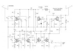
The following diagram is the Theremin music instrument effect. A guitar or instrument amplifier is an ideal companion unit for the theremin; either one allows bass or treble boost, as desired, and fuzz (distortion) or reverberation (if these features are incorporated in the amplifier’s circuit). Simply provide a suitable cable plug and connect the theremin’s output cable to the amplifier’s input jack.
(View)
View full Circuit Diagram | Comments | Reading(876)
Tube Distortion Pedal
Published:2013/3/27 3:49:00 Author:Ecco | Keyword: Tube Distortion Pedal
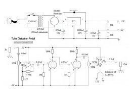
The following circuit is Tube Distortion Pedal for guitar effect. The circuit designed by Ron Black. Notes: IC1 : 747 dual op-amp, other ICs may be substitued but pinout will different. You should check the datasheet IC2 : LM340K-12V Voltage Regulator All resistors are 1/2 W Bridge Rectifier – Full wave bridge recitifier, 50 Volts, 500 mA minimum.
(View)
View full Circuit Diagram | Comments | Reading(1215)
Surround Sound Decoder
Published:2013/3/27 3:48:00 Author:Ecco | Keyword: Surround Sound Decoder
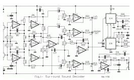
The following diagram is an small surround sound decoder schematics. You may use this decoder surround sound systems for your home audio system. Parts List: R1-2-7-8-12-13-18-19-20=47Kohm R3-4-5-6-21-22-34-35=10Kohm R9-10-11-14-15-16-17=15Kohm R=23-24-25-33-36=100ohm R26-27-28-31-32=100Kohm R29-30=5.6Kohm C1-8=47uF 25V C2-7-9-14-23=47nF 100V C3-6=1uF 100V C4-5-10=33pF 100V C11-12-15=10uF 25V C13=82nF C16=18pF 100V C17=100pF mini adjustable capacitor C18=2.2nF C19=4.7uF 25V C20=100nF 100V C21=10nF C22=180pF C24=150nF RV1-RV2=2X10Kohm Log. pot. RV3-4=10K Log pot. D1=1N4148 IC1-6=TL072 IC2-3=TL074 IC4=MN3101 IC5=MN3004 JI…..J6=RCA female jack
(View)
View full Circuit Diagram | Comments | Reading(984)
A/B Box Guitar Effect Schematic
Published:2013/3/27 3:45:00 Author:Ecco | Keyword: A/B Box Guitar Effect
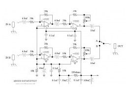
This is a A/B Box pedal schematic for electric guitar was designed by Rick Barker. This A/B Box effect was originally designed for switching between different harmonica mics. This A/B Box featured low noise dual preamp for better effect.
(View)
View full Circuit Diagram | Comments | Reading(1104)
Simple Mixer
Published:2013/3/27 3:44:00 Author:Ecco | Keyword: Simple Mixer

Here the simple mixer with 4 input and 2 op-amps: A basic mixer suitable for mixing microphones or even effects outputs. The overall gain from input to output is one if the pot related towards the input is full up. You can make this a net gain of ten (or any other reasonable gain) by reducing the input resistor towards the second op amp.
(View)
View full Circuit Diagram | Comments | Reading(1592)
Maestro Boomerang
Published:2013/3/27 3:43:00 Author:Ecco | Keyword: Maestro Boomerang
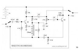
Here the circuit diagram of Maestro Boomerang / Wah-Wah Pedal for electric guitar effect. Note: Transistors Q1 and Q2 were designated P-2356
(View)
View full Circuit Diagram | Comments | Reading(721)
Dallas Arbiter Fuzz Face
Published:2013/3/27 3:41:00 Author:Ecco | Keyword: Dallas Arbiter Fuzz Face
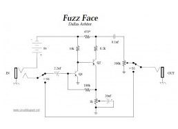
This is the circuit diagram of Fuzz Face mods, guitar effect pedal. This is a modified diagram and simpler than the original Fuzz Face diagram. You will find apparently two identical designs of the fuzz face. In one Q1 and Q2 had been PNP germanium AC128 or NKT275 types, in the other they had been NPN sillicon BC108C types.
(View)
View full Circuit Diagram | Comments | Reading(1134)
Jimi Hendrix Fuzz Face Pedal
Published:2013/3/27 3:40:00 Author:Ecco | Keyword: Jimi, Hendrix Fuzz Face Pedal
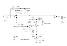
The following diagram is the Jimi Hendrix Fuzz Face Pedal circuit diagram. Schematic by Jim Dunlop Note: Q1 & Q2 are MPSA18.
(View)
View full Circuit Diagram | Comments | Reading(1167)
Motion Filter Effect
Published:2013/3/27 3:40:00 Author:Ecco | Keyword: Motion Filter Effect
This circuit will controls the initial frequency and controls how much the envelope follower responds to the input signal. An envelope follower/filter combination translates the typical dynamic properties of your axe into modulated timbral changes too, you could feel of it as an automatic wah-wah pedal.
(View)
View full Circuit Diagram | Comments | Reading(620)
Mesa Boogie Dual Rectifier
Published:2013/3/27 3:39:00 Author:Ecco | Keyword: Mesa Boogie , Dual Rectifier
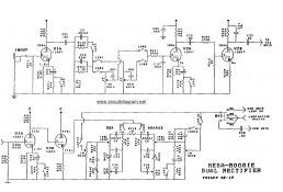
The following diagram is Dual Rectifier schematic diagram. This is a tubed pre-amp and tubed amplifier designed and manufactured by Mesa Boogie. This Mesa Boogie Dual Rectifier available to download in pdf document. You will find the complete diagram of this dual rectifier there.
(View)
View full Circuit Diagram | Comments | Reading(2712)
Four monostable circuit
Published:2013/3/25 2:42:00 Author:Ecco | Keyword: Four monostable, circuit
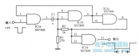
Four monostable circuit is shown as figure.
(View)
View full Circuit Diagram | Comments | Reading(592)
Zener diode controlled Wien bridge
Published:2013/3/25 2:48:00 Author:Ecco | Keyword: Zener diode , Wien bridge
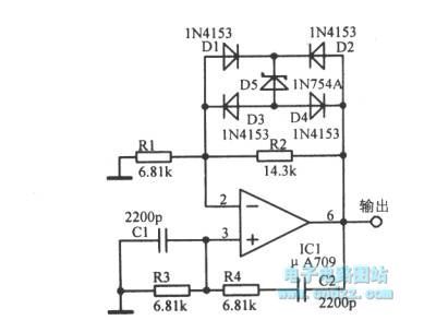
Zener diode controlled Wien bridge is shown as figure.
(View)
View full Circuit Diagram | Comments | Reading(1564)
Orange 125MK3 Guitar Mods
Published:2013/3/26 3:45:00 Author:Ecco | Keyword: Orange , Guitar Mods

This document contains schematic diagram of Orange 125MK3 including the guitar preamp section, feedback and power amplifier section.
(View)
View full Circuit Diagram | Comments | Reading(646)
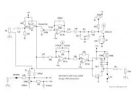
Tube Head
Published:2013/3/26 3:44:00 Author:Ecco | Keyword: Tube Head

This is a simple and low cost Tube Head Vacuum Tube pre-amp circuit designed bu PAiA electronics: Vcc – Pin 1 IC1 +12v – Pin 8 IC2, IC3, IC4 -12v – Pin 4 IC2, IC3, IC4 Ground – Pin 8 IC1 IC1 – 4049 CMOS Hex Inverting Buffer IC2
(View)
View full Circuit Diagram | Comments | Reading(1722)
| Pages:45/471 At 204142434445464748495051525354555657585960Under 20 |
Circuit Categories
power supply circuit
Amplifier Circuit
Basic Circuit
LED and Light Circuit
Sensor Circuit
Signal Processing
Electrical Equipment Circuit
Control Circuit
Remote Control Circuit
A/D-D/A Converter Circuit
Audio Circuit
Measuring and Test Circuit
Communication Circuit
Computer-Related Circuit
555 Circuit
Automotive Circuit
Repairing Circuit