
Index 48
Nine Volt Battery Eliminator
Published:2013/3/10 22:15:00 Author:Ecco | Keyword: Nine Volt, Battery Eliminator
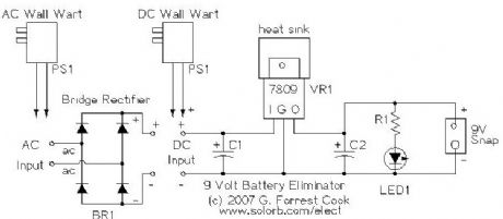
Effect pedals for electric guitars are typically powered by 9 volt batteries. These batteries cost several bucks each and don't often last very long. Leaving a pedal turned on overnight by accident guarantees a dead battery in the morning. Why spend your precious money on a constant supply of batteries when you can build this easy substitute that won't fade away right in the middle of that killer guitar solo. This device is not limited to use in guitar pedals, it can be used with guitar tuners, radios and other small 9V devices. The circuit can be built to support DC or AC wall warts, the AC version requires a bridge rectifier. I've build many of these out of surplus materials, they make good gifts for guitar players.
(View)
View full Circuit Diagram | Comments | Reading(2330)
Spartacus Hammond AO-44 Organ to Guitar Amp Conversion
Published:2013/3/10 21:54:00 Author:Ecco | Keyword: Spartacus , Hammond Organ , Guitar Amp Conversion

This amplifier is a variation on the Hammond AO-44 Reverb Amp to Hi-Fi Amp Conversion project. The goal is slightly different: the Spartacus amp has more gain and higher output power, making it better for use as a guitar amplifier. Unlike the previous project, the Spartacus amp involves a complete rewire of the Hammond AO-44 chassis. The hard to find 6GW8/ECL86 tubes are replaced with more common and higher power 6BQ5/EL84 tubes. Output power is around 12 Watts, that may not seem like much, but the amp can get quite loud. A cool looking 6U10 compactron triple triode is added to the amp's chassis, it provides the first two gain stages and the phase inverter stage.
The name Spartacus was inspired by the ancient slave who broke free from the Romans and wreaked havoc for many years. Like its namesake, the amp makes an excellent stereo guitar slave amp when used in conjuction with projects such as the Hammonator 2RVT and Lil' Tiger amps. The Spartacus amp can also break free and function as an independent amp, it works nicely with a 12 guitar speaker.
The Hammond AO-44 amplifier chassis can be found on eBay for reasonable prices. The Spartacus design is simple and clean. The wiring is dense, but not overly difficult to assemble. The controls include the basic volume, bass and treble adjustments as well as a gain control. The gain (negative feedback) control is more than just a second volume control, it adjusts the the character of amplifier's sound from compressed and tight to open and loud like the popular Fender 5E3 amp.
(View)
View full Circuit Diagram | Comments | Reading(2705)
Fuzzy Firebottle Guitar Distortion Pedal
Published:2013/3/10 21:52:00 Author:Ecco | Keyword: Fuzzy Firebottle, Guitar Distortion Pedal

Power is supplied to the device from a 12VDC wall-wart transformer supply. Be sure that the wall-wart really produces 12VDC, many of these devices only produce their rated voltage at a given load current. A LM7812 voltage regulator (with a heat sink) may be used between a 14-18VDC unregulated supply and the distortion circuit. The +12VDC supply is initially filtered with a 1000uF capacitor, it is further filtered to the +12Vf1 and +12Vf2 supplies through two more R/C lowpass sections.
The +30VDC tube plate supply voltage is produced by an LMC555 CMOS timer chip set to generate square waves. The square waves are fed to a voltage tripler circuit which produces around 30VDC. The tripler uses 1N5818 Schottky diodes instead of regular silicon diodes to produce the full 30V. The +30V supply is filtered through the 1K and 470uF RC lowpass filter before being sent to the 12AX7 plate circuits (B+). The tube filament supply is provided directly from the +12VDC supply line.
The guitar audio signal is fed to the 2N3906 amplifier stage via a 100K input gain potentiometer. The 2N3906 bias is set to a fixed (class A) level by the 20K trimmer potentiometer. The 27 ohm emitter resistor provides negative feedback to limit the maximum gain for the 2N3906 amplifier stage. The output of the 2N3906 amplifier produces the clean signal for the mixer and the input drive to the first of the 12AX7 triode sections.
The clean signal is sent to the LM311 + input in the clipping circuit. The LM311 - input is set to a fixed 6.9VDC level. When the 2N3906 emitter signal goes above 6.9VDC with large input signals, the LM311 output signal switches from low to high. This is fed through the 100nF capacitor to the input of the LMC555 pulse stretcher circuit (one shot). On the return from high to low, the pulse stretcher triggers and the the amber LED blinks on for a few tens of milliseconds to indicate clipping.
The clean audio signal is sent to the grid of the first 12AX7 section through the 100K drive control. If the drive control is set high, the signal on the first 12AX7 plate is distorted. The plate signal from the first 12AX7 section is fed to the second drive control via a 50nF DC blocking capacitor. The signal on the second 12AX7 plate is even more distorted. The distorted signal from the second 12AX7 plate is sent through a 50nF DC blocking capacitor and fed to the Mix control.
The High Cut switch optionally puts a 68K/330pF or 68K/1nF RC filter to reduce the high frequency harmonics. The center tap of the Mix control contains a mix of the clean and distorted signals. This is sent to the Output Level control and switched to the Output jack via the foot switch and through the 100K/47K attenuator.
(View)
View full Circuit Diagram | Comments | Reading(1450)
Liquidator Tube Phaser/Chorus Effect
Published:2013/3/10 21:50:00 Author:Ecco | Keyword: Liquidator Tube, Phaser, Chorus Effect

This project involves the conversion of a Hammond AO-47 organ vibrato unit (Original Hammond Schematic) into a 4 phase guitar/music phaser/chorus box. The individual phase signals can be mixed for a wide variety of sounds. The Liquidator name comes from the liquidy sounds that the device creates, it wiggles the audio all around. Used Hammond vibrato units can often be purchased for little money on eBay and provide the majority of the circuitry for this device. The Hammond AO-41 box can also be used for this project, it has one extra 7 pin tube socket. The Liquidator's companion project is the FuzzniKator Tube Distortion/Preamp.
Builders should have decent technician and metalworking skills to build this project. A chassis and power supply with input output jacks, power line, knobs and switches needs to be constructed. The AO-47 box needs many soldering modification to convert it to the phaser/chorus circuit. Additionally, an LFO circuit needs to be constructed from an Arduino microprocessor platform to make the appropriate control waveforms. Thanks to the tube circuitry, the audio quality of this phaser is superior to a transistor or op-amp based phaser, the level of hiss is very low.
(View)
View full Circuit Diagram | Comments | Reading(3239)
Lil Tiger Hammond AO-43 Organ to Guitar Amp Conversion
Published:2013/3/10 21:48:00 Author:Ecco | Keyword: Lil Tiger, Hammond Organ , Guitar , Amp Conversion

This project follows in the footsteps of the Hammonator and Hammonator 2RVT organ amplifier to guitar amplifier conversion projects. A variety of Hammond tube amps are available on eBay for reasonable prices and they make a good platform for a guitar amplifier project. The Hammond AO-43 chassis is a prime candidate for conversion, it is large enough to build a full-featured amp with reverb and other effects and has a bare side that can hold many knobs and jacks.
This amp has undergone a number of design changes since the original version was published. A second copy of the amp was constructed and the reverb driver tube was changed from a 6SN7 to a more period-correct 6FQ7/6CG7. The reverb driver circuitry was changed to include a Reverb Send control, this gives the amp a much wider variety of reverb sounds. The volume and reverb return controls have been wired in a mixer configuration which is somewhat unusual for amp designs. This makes it possible to listen to the reverb channel by itself or to have a mix with very heavy reverb. The vibrato circuit was also rebiased to produce a more intense effect. I liked the rev 2 modifications enough that I applied them to the original amp.
The output stage of this amplifier uses 6BQ5/EL34 pentodes wired in a cathode-biased push-pull configuration, audio power output is around 15W. In the Hammonator project, almost all of the original circuitry was replaced. In this amp, most of the original power amp circuitry was reused. It is important to replace all of the electrolytic capacitors with new parts or bridge new capacitors across the old ones since the original capacitors have probably dried up and become lower in value. All of the resistors should be checked to verify the correct value, old resistors that are run hot tend to go up in value and should be replaced.
The vibrato is somewhat subtle when the amp is played by itself. To get the best vibrato effect, a second amplifier should be plugged into Guitar Input 2 to tap into the input signal. The resulting stereo signal moves around the room in a manner that sounds a lot like a rotating Leslie speaker. Beware, once you get used to playing through a stereo setup all other amps will sound flat.
One could consider this to be a left-handed amp, the signal path and knobs are mostly right to left. The chassis tube layout made this necessary.
(View)
View full Circuit Diagram | Comments | Reading(4141)
Hammonator 2RVT Organ to Guitar Amp Conversion
Published:2013/3/10 21:46:00 Author:Ecco | Keyword: Hammonator, Organ , Guitar, Amp Conversion

This project is a feature-added version of the Hammonator 1 Hammond organ to guitar amplifier conversion project. The Hammonator 1 circuit worked as a basic guitar amplifier, this version adds some very nice sounding vacuum tube audio effects. The 2RVT model number means: 2nd Generation, Reverb, Vibrato and Tremolo. Two copies of the Hammonator 2RVT amp have been made (see photos), both have been working nicely for years. The design has stood the test of time.
The reverb uses a classic sounding tube circuit with a class A triode driving an 18 reverb pan. The reverb has both dwell (input) and output level controls. A pitch-shifting vibrato / volume shifting tremolo circuit is part of the signal path. The vibrato produces a variety of interesting phase shift sounds, from slow movement to warbling.
Stereo vibrato can be easily achieved by chaining a second clean cannel amp's input to the Hammonator's second input jack, or by driving the amp from the Side Channel Output connection. Stereo greatly enhances the vibrato effect, the sound appears to move around the room. A cheap guitar practice amp makes an ok secondary amp, a tube amp such as the Spartacus or the Howler Monkey will produce an even better sound. The Tremolo/vibrato switch changes the pitch shifting vibrato effect into a volume shifting tremolo effect. The wide range of LFO speeds produce some interesting tremolo effects.
(View)
View full Circuit Diagram | Comments | Reading(934)
Hammonator Organ to Guitar Amp Conversion
Published:2013/3/10 21:44:00 Author:Ecco | Keyword: Hammonator Organ, Guitar Amp Conversion

In the world of electronics, vacuum tubes are almost obsolete. Nearly the last holdout, the cathode ray tube (CRT), is rapidly being replaced by the LCD and other new technologies. Despite this trend, the vacuum tube has seen a big revival in the field of guitar amplifiers, and to a lesser extent, hi-fi amplifiers. Vacuum tubes and related parts have become more readily available in recent years as numerous companies have tapped into this market.
The reason for the popularity of tubes in guitar amps involves the nice tones that are produced when tubes are driven to the point of distortion. For some background on this, follow some of the links on The Strat Monger. There are numerous solid state modeling amps that try to simulate vacuum tube amps with digital signal processing (DSP) techniques, but in the end, that method is never more than a simulation. It just ain't the same as the real thing.
One can spend a large amount of money and time building a tube amp from scratch. Hammond organ ampifiers chassis are available on the surplus market for a reasonable price, they make a good starting point for a guitar amp. The difficult job of cutting chassis holes for the tubes and transformers is already done, one just needs to drill a few holes for the potentiometers and connectors. This project started with the amplifier from a Hammond M2 organ, chassis model AO14-1B.
The output stage of this amplifier resembles a fusion between a Fender Princeton Reverb, Fender Vibroverb and ham radio transmitter. With 6V6 output tubes running at a 420V plate voltage, it puts out approximately 18 watts of audio power. The 17 reverb tank provides a deep echoey sound. The simpler is better philosophy was used in the design, multiple inputs with their own preamp stages were intentionally avoided to reduce hiss. The amp is plenty loud, and the sound quality is excellent. The Hammonator amp has worked well driving both 12 and 15 guitar speakers.
(View)
View full Circuit Diagram | Comments | Reading(2138)
The Little Chickadee 6U8A QRP Transmitter
Published:2013/3/7 3:11:00 Author:Ecco | Keyword: Little Chickadee , QRP Transmitter

The triode section of the 6U8A is used as a tuned crystal oscillator stage in the crystal version of the circuit and a tuned amplifier in the VFO version. The triode's tuned circuit consists of L1, a fixed-value silver mica capacitor and a ceramic compressions trimmer capacitor. For 80 meter operation, the silver mica capacitor should be 130pf and for 40 meter operation, the capacitor should be 22pF. L1 is made with 47 turns of #24 insulated wire on a 3/8 air core cardboard form, this works for both 40 and 80 meters. The trimmer capacitor should be adjusted so that the circuit resonates at the crystal frequency. Resonance can be observed with an oscilloscope, the probe should be lightly coupled to the oscillator plate, connect the scope probe to the plate via a small capacitor such as 5pF.
The crystal version of this transmitter is rock bound to a particular frequency. Common 3.58 Mhz crystals can be used, but this frequency tends to be occupied by digital-mode signals. It is a good idea to use the crystal oscillator (VXO) variable capacitor to shift the frequency up a few kilohertz to a quiet spot on the band. Other frequencies can be used by switching different crystals into the circuit or using a crystal socket. The oscillator's tank circuit should be re-peaked for different crystals if they are more than a few tens of kiloherz apart in frequency.
(View)
View full Circuit Diagram | Comments | Reading(1841)
Morse Code Beacon Keyer
Published:2013/3/7 3:07:00 Author:Ecco | Keyword: Morse Code , Beacon Keyer

This circuit stores a morse code message as bits in an EPROM chip, the message is sent to a relay which can key a CW transmitter. The keyer can output either a one-shot message such as CQ DX DE CALLSIGN , or a continuous message. The continuous mode is useful for making beacons for low power (QRP) and slow (QRSS) transmissions. A One-shot message can be controlled by pressing the start/stop buttons, a continuous message can be sent by turning on the free run switch.
EPROMs other than the 2732 can be used if suitable changes are made to the address lines in the circuit. For larger EPROMs, just ground the higher order address input lines on the EPROM chip, and wire the appropriate chip select pins for outputs enabled and chip selected.
It is also possible to store more than one message in different banks of a larger EPROM, for instance, if a 2764 part were used, the A12 address line could be used to select the upper or lower message.
Note that the photo above shows a slightly different implementation of the circuit. A 5V power supply and a 555 timer sidetone oscillator have been added, the keyer relay has been removed and the EPROM is a 2716 type.
(View)
View full Circuit Diagram | Comments | Reading(1501)
Wien bridge AF / RF circuit
Published:2013/3/7 2:32:00 Author:Ecco | Keyword: Wien bridge, AF, RF circuit

Wien bridge AF / RF circuit is shown as figure.
(View)
View full Circuit Diagram | Comments | Reading(589)
Solar Panel Current Meter
Published:2013/3/6 3:22:00 Author:Ecco | Keyword: Solar Panel , Current Meter

This circuit is used to measure the current from a solar panel. It has very low power loss for currents in the 0-10A range. It also works as a general purpose DC current meter. The circuit can be used on either the positive or negative side of a DC circuit.
(View)
View full Circuit Diagram | Comments | Reading(850)
Expanded Scale Battery Volt Meter
Published:2013/3/6 3:21:00 Author:Ecco | Keyword: Expanded, Scale Battery, Volt Meter

This circuit is used to measure the voltage on a 12V (nominal) lead acid rechargeable battery system. It was specifically designed for use in solar powered systems, but is general enough that it can be used for automotive or other 12V systems. Lead acid batteries normally spend their working lifetime in the voltage range of 11-15 Volts. This meter circuit was designed to show the voltage range of 10-15V on an analog meter movement, it can be used to show the battery charge state from empty to full.
(View)
View full Circuit Diagram | Comments | Reading(927)
WGR1 - 12 Volt Wind Generator Regulator
Published:2013/3/6 3:20:00 Author:Ecco | Keyword: 12 Volt, Wind Generator, Regulator

The WGR1 circuit is used to regulate the charging of a lead acid battery system from a DC-output wind generator. It consumes minimal power when idle and efficiently delivers charging power to the battery when the wind generator is up to speed. Excess charging power is diverted to a large dump resistor, the heat produced can be used to keep the battery warm when used in cold climates. The WGR1 circuit is designed to operate in conjuntion with a photovoltaic (solar) charge controller such as my SCC3 design.
The WGR1 circuit features make-before-break switching. This ensures that the current from the wind generator is either going to the battery, to the load, or very briefly to both during switching times. By managing the switching this way, high voltage transients are minimized, protecting the MOSFET transistors. The make-before-break switching also guarantees that there will always be a load on the wind generator. Unloaded wind generators tend to spin out of control and may even self-destruct.
This project came about after my 400W Southwest Windpower air-X wind generator was exposed to winds in excess of 120Mph (above the unit's maximum rated wind speed), causing the internal control electronics to burn out. The air-X internal regulator was replaced with a set of six high-current diodes wired in a standard 3-phase bridge rectifier configuration. The resulting pulsating DC voltage is fed to this circuit via some heavy-duty wiring. (View)
View full Circuit Diagram | Comments | Reading(3365)
SPC2 6 Amp Solar Power Center
Published:2013/3/6 3:16:00 Author:Ecco | Keyword: 6 Amp, Solar Power Center

The SPC2 is a solar power center, it can be used to handle all of the power functions for small 12 Volt solar powered devices. It contains a photovoltaic charge controller and a low voltage load disconnect circuit. The low voltage disconnect has a load on-off switch, and a battery low voltage indicator. By using the SPC2 as the center of a solar powered device, long battery life is assured. The SPC2 is primarily designed to be a solar lighting controller, it can be used to power radios and other high capacitance loads with a minor switch and circuit modification (shown in dotted lines on the schematic). (View)
View full Circuit Diagram | Comments | Reading(4200)
LVD1 Circuit Extensions
Published:2013/3/6 2:54:00 Author:Ecco | Keyword: Extensions

It is easy to invert the logic of the LVD1 output circuit, this can be useful if you want to automatically activate an AC-operated battery charger or a backup generator when your battery gets low. The above circuit shows the modification to the LVD1 schematic for inverting the output logic. The LVD1 load connection can drive an AC-output solid state relay to switch on power to a backup AC-operated charger, a DC-output solid state relay can be used to control a generator starter circuit.
The AC charger should be tested to see if its DC output connection consumes reverse current from the system battery when the charger is off. If this occurs, a suitably rated Schottky diode should be put between the AC charger's output terminals and the battery to prevent the reverse current from discharging the battery.
(View)
View full Circuit Diagram | Comments | Reading(655)
LVD1 - 12 Volt 15 Amp Low Voltage Disconnect
Published:2013/3/6 2:53:00 Author:Ecco | Keyword: 12 Volt, 15 Amp , Low Voltage Disconnect

This circuit provides a low voltage disconnect (LVD) function for battery operated 12 Volt DC power systems. It is ideal for use with solar powered battery systems. The LVD1 circuit is designed to protect a battery from excessive discharge. Rechargeable batteries will have a much longer life if they are never allowed to discharge below the manufacturer's recommended minimum voltage.
The LVD1 circuit supports common-ground loads by switching the high side of the load on and off. The LVD1 circuit is protected against reverse battery connection. This circuit is designed to be used in conjunction with the SCC3 solar charge controller, LVD1 and SCC3 kits are available from CirKits.
The circuit features both Automatic and Manual modes of operation. The controls include an On-Off power switch and an On-Off-(On) switch for selecting the Auto-on and (Manual-on) modes of operation. An isolated low voltage detect signal is provided by the circuit, this can be monitored by a computer for a controlled shutdown prior to the disconnection of power. (View)
View full Circuit Diagram | Comments | Reading(2128)
VOLTAGE DOUBLER Circuit
Published:2013/3/5 21:07:00 Author:Ecco | Keyword: VOLTAGE DOUBLER

A voltage higher than the supply can be created by a Charge-Pump circuit created with a 555, diodes and capacitors as shown in the following circuit. The output will deliver about 50mA.
(View)
View full Circuit Diagram | Comments | Reading(1219)
WAILING SIREN Circuit
Published:2013/3/5 21:03:00 Author:Ecco | Keyword: WAILING SIREN

By pressing the button, the wailing sound increases. Releasing the button decreases the wailing. The circuit automatically turns off after about 30 seconds.
(View)
View full Circuit Diagram | Comments | Reading(1330)
UNEVEN CLICKS Circuit
Published:2013/3/5 21:02:00 Author:Ecco | Keyword: UNEVEN CLICKS
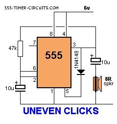
This circuit produces two clicks then a short space before two more clicks etc. Changing the voltage on pin, 5 via the diode, adjusts the timing of the chip.
(View)
View full Circuit Diagram | Comments | Reading(553)
TOY ORGAN Circuit
Published:2013/3/5 20:56:00 Author:Ecco | Keyword: TOY ORGAN

A circuit that produces 5 different sounds. Overview This circuit produces a tone according to the button being pressed. Only 1 button can be pressed at a time, that's why it is called a monophonic organ. You can change the 1k resistors to produce a more-accurate scale.
(View)
View full Circuit Diagram | Comments | Reading(1270)
| Pages:48/471 At 204142434445464748495051525354555657585960Under 20 |
Circuit Categories
power supply circuit
Amplifier Circuit
Basic Circuit
LED and Light Circuit
Sensor Circuit
Signal Processing
Electrical Equipment Circuit
Control Circuit
Remote Control Circuit
A/D-D/A Converter Circuit
Audio Circuit
Measuring and Test Circuit
Communication Circuit
Computer-Related Circuit
555 Circuit
Automotive Circuit
Repairing Circuit