
Index 46
5 Band Graphic Equaliser
Published:2013/3/26 3:38:00 Author:Ecco | Keyword: 5 Band, Graphic Equaliser

This is the diagram of 5 band graphic equaliser circuit. The circuit is based on operational amplifier, the NE5532 or LM833 is the right choice for low cost op-amp chip with fairly good quality output. Each IC contains dual op-amps circuit, so you will need 4 ICs of NE5532 or LM833 to build this 5 band graphic equaliser.
(View)
View full Circuit Diagram | Comments | Reading(801)
Electro-Harmonix Small Stone Phaser Guitar Effect
Published:2013/3/26 3:34:00 Author:Ecco | Keyword: Electro-Harmonix , Small Stone Phaser, Guitar Effect

This is the schematic diagram of Electro-Harmonix Small Stone Phaser guitar effect pedal. The Small Stone is somewhat special in applying Operational Transconductance Amplifiers (OTA’s) for phase shift stages rather of opamps with variable resistors. All of the IC’s are house marked EH1048, but could be replaced with CA3094 that is a combination of an OTA equal with the CA3080 as well as a darlington emitter follower.
(View)
View full Circuit Diagram | Comments | Reading(2610)
DOD FX75 Flanger Guitar Effect Pedal
Published:2013/3/26 3:16:00 Author:Ecco | Keyword: DOD , Flanger Guitar, Effect Pedal

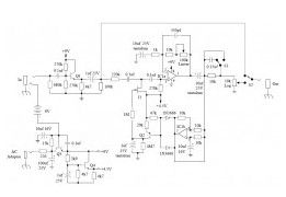
This is the circuit diagram of DOD FX75 Flanger guitar effect pedal. The circuit drawn by Fabian P. Hartery Components description: CD4007 dual complementary pair with inverter; (RCA) TL022C low power dual operating amplifier; (texas instruments) MN3007 audio signal delay, 1024 stage low noise BBD (5.12-51.2 msec delay) MN3101 clock generator for Bucket Brigade Device/BBD MN3101/MN3007 manfufactured by Panasonic.
(View)
View full Circuit Diagram | Comments | Reading(1282)
Gibson RD Artist Guitar
Published:2013/3/26 3:14:00 Author:Ecco | Keyword: Gibson RD Artist Guitar

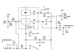
The following diagram is the schematic of Gibson RD Artist bass guitar Circuit Notes: Both compression and expansion effects are determined by the lead pickup output only. I and O in the design diagram refer to inner and outer connections for the specific plug / jack. P and J in the design diagram refer to plugs and jacks respectively.
(View)
View full Circuit Diagram | Comments | Reading(976)
Vox Tone Bender Pedal
Published:2013/3/26 3:13:00 Author:Ecco | Keyword: Vox Tone Bender Pedal

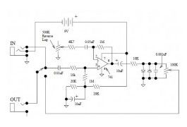
This is the circuit diagram of Vox Tone Bender Pedal. The circuit is very similar to Fuzz Face pedal. The Vox ToneBender will have a lot more treble response than the Fuzz Face…maybe to help brighten up those characteristically “dark” sounding British amps some.
(View)
View full Circuit Diagram | Comments | Reading(740)
Univox Super-Fuzz Pedal
Published:2013/3/26 3:12:00 Author:Ecco | Keyword: Univox Super-Fuzz Pedal

This is the circuit diagram of Univox Super-Fuzz Pedal. This pedal is actually a 69-to-early 70’s design that consists of two special capabilities. They are the octave generation effect from the differential-pair-with-collectors -tied-together along with the option of just a clipping amplifier or a 1kHz notch for different sounds.
(View)
View full Circuit Diagram | Comments | Reading(959)
UniVibe Pedal
Published:2013/3/26 3:11:00 Author:Ecco | Keyword: UniVibe Pedal

The Univibe is actually a footpedal-operated phaser or phase shifter for generating chorus and vibrato simulations for electric organ or guitar. It was introduced in the 1960s by Shin-ei, and was intended to emulate the “Doppler sound” of a Leslie speaker.
(View)
View full Circuit Diagram | Comments | Reading(1237)
Octave Fuzz Pedal
Published:2013/3/26 3:10:00 Author:Ecco | Keyword: Octave Fuzz Pedal

Here the circuit diagram of octave fuzz guitar effect pedal. This guitar effect unit is great sounding octave fuzz, with an optional mode of just fuzz. The fuzz is really a absolutely rectified signal and is fairly chewy.
(View)
View full Circuit Diagram | Comments | Reading(1259)
DOD Overdrive 250
Published:2013/3/26 3:10:00 Author:Ecco | Keyword: DOD Overdrive 250
This is the DOD Overdrive 250 preamp circuit diagram. The DOD Overdrive 250 is Yet Another 741 With Two Diodes On The Output channel. It is almost exactly the same as the MXR Distortion Plus, and a number of other units.
(View)
View full Circuit Diagram | Comments | Reading(1236)
Tube Sound Fuzz
Published:2013/3/26 3:05:00 Author:Ecco | Keyword: Tube Sound Fuzz

This Tube Sound Fuzz circuit is taken from the book of Electronic Projects for Musicians by Craig Andertons. This circuit applies a CD4049 Hex inverter, which consists of six inverting units, only two are being used in this circuit, so the others are disabled by connecting their inputs to the positive voltage source and leaving the output disconnected.
(View)
View full Circuit Diagram | Comments | Reading(1244)
Western Music Generator based IC HT82207
Published:2013/3/26 3:05:00 Author:Ecco | Keyword: Western Music Generator

This is the schematic diagram of Western music generator circuit based on single IC HT82207. This circuit is able to take you towards the world of the Wild West. The western music already programmed in the chip. It utilizes the integrated 18-pin HT82207 (IC1) of Holtek, which literally takes care of almost everything.
(View)
View full Circuit Diagram | Comments | Reading(1337)
Hi-Fi Compressor with Pre-emphasis
Published:2013/3/26 3:03:00 Author:Ecco | Keyword: Hi-Fi Compressor, Pre-emphasis
Here is the Hi-Fi compressor circuit with pre-emphasis. The above diagram is a circuit for a high fidelity compressor which uses an external op-amp and has a high gain and wide bandwidth. An input compensation network is required for stability.
(View)
View full Circuit Diagram | Comments | Reading(0)
Electro-Harmonix Soul Preacher
Published:2013/3/26 2:59:00 Author:Ecco | Keyword: Electro-Harmonix Soul, Preacher
This is the circuit diagram of Electro-Harmonix Soul Preacher pedal.
(View)
View full Circuit Diagram | Comments | Reading(943)
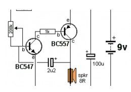
Cheap Hearing Aid
Published:2013/3/25 4:30:00 Author:Ecco | Keyword: Cheap Hearing Aid
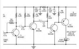
Here the cheap hearing aid to help people who have hearing loss. Commercially available assistive hearing devices are quite expensive. This is a cheap hearing aid device circuit which works by using just four transistors and several passive electronic components.
(View)
View full Circuit Diagram | Comments | Reading(872)
Ticking Bomb Sound Generator
Published:2013/3/25 4:29:00 Author:Ecco | Keyword: Ticking Bomb, Sound Generator
Here the low cost and easy build circuit of ticking bomb sound generator. This circuit generates a sound matching to a loud clicking clock. The frequency of the tick is altered through the 220k potensiometer part. The circuit gets going by charging the 2.2uF and when 0.65v is on the base of the NPN transistor, it begins to turn on
. (View)
View full Circuit Diagram | Comments | Reading(989)
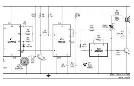
Electronic Horn
Published:2013/3/25 4:29:00 Author:Ecco | Keyword: Electronic Horn
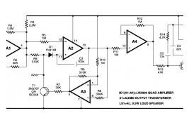
This is an easy, low cost and easy built circuit of an electronic horn which is designed close to quadruple op-amp IC LM3900 (IC1). IC LM3900 has four independent operational-amplifiers (A1 through A4) having a large output voltage swing. It is able to operate at up to 32V DC. (View)
View full Circuit Diagram | Comments | Reading(857)
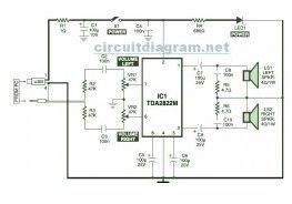
USB Powered, Stereo Computer Speaker
Published:2013/3/25 4:27:00 Author:Ecco | Keyword: USB Powered, Stereo Computer Speaker
View full Circuit Diagram | Comments | Reading(867)
Beeper Sound
Published:2013/3/25 4:16:00 Author:Ecco | Keyword: Beeper Sound
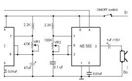
This is the circuit diagram of beeper sound. The circuit will generate the sound of a beeper which similar with the one in pagers. It produces a “beep-beep” sound. The work of this circuit is simple, the circuit applied the 555 timer oscillator which is turned ON and OFF periodically.
(View)
View full Circuit Diagram | Comments | Reading(678)
Heat Detector + Siren
Published:2013/3/25 3:49:00 Author:Ecco | Keyword: Heat Detector, Siren
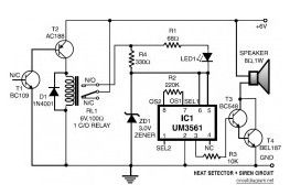
This is the diagram of heat detector circuit which already integrated with siren circuit in the output. This circuit applies a complementary pair comprising NPN metallic transistor T1 (BC109) and PNP germanium transistor T2 (AC188) to detect heat (because of outbreak of fire, for example) in the area and activate a siren/alarm.
(View)
View full Circuit Diagram | Comments | Reading(928)
Shutter Guard
Published:2013/3/25 3:45:00 Author:Ecco | Keyword: Shutter Guard
This is the shutter guard circuit which has sensitive vibration sensor, piezo-sensor. This circuit is specifically designed for outlets to defend towards theft. It can recognize any mechanical or acoustic vibration in its area when somebody attempts to break the shutter and instantly turn on a lamp and sound an alert alarm.
(View)
View full Circuit Diagram | Comments | Reading(816)
| Pages:46/471 At 204142434445464748495051525354555657585960Under 20 |
Circuit Categories
power supply circuit
Amplifier Circuit
Basic Circuit
LED and Light Circuit
Sensor Circuit
Signal Processing
Electrical Equipment Circuit
Control Circuit
Remote Control Circuit
A/D-D/A Converter Circuit
Audio Circuit
Measuring and Test Circuit
Communication Circuit
Computer-Related Circuit
555 Circuit
Automotive Circuit
Repairing Circuit