
Index 91
Digital pressure signal disposal device MAX1458 bridge excitation circuit
Published:2011/8/31 1:51:00 Author:Jessie | Keyword: Digital pressure signal disposal device, bridge excitation

Digital pressure signal disposal device MAX1458 bridge excitation circuit is shown in figure. Using DAC3's outputcan change sensor incentive current IBR's value, then itwillrealize full range fine calibration. IISRC is benchmark current, and it is set by the voltage of RISRC and pin 9. V1 and V2form mirror current sourcem, current gain is 14 times, and it can make incentive current IBR=14IISRC. IBR's programming rangeis 0.1~2mA. Analog switches S1, S2's hige state is controlled by configuration register. Obviously, when full range output voltage changes, DAC3 will compensate bridge road output voltage by changing BR, and correct full range error. DAC4 is used tocorrect full range temperature coefficient error. (View)
View full Circuit Diagram | Comments | Reading(597)
Digital electric clock circuit diagram
Published:2011/8/30 1:56:00 Author:Jessie | Keyword: Digital electric clock


As shown in figure, digital electric clock circuituses electronic horologe special integrated circuit KD482FCas seconds time-base signal. Through the digital circuit multi-stage separate frequency, it formsminute and hour to output. The minute isdisplayed byLED digital tube; While hour display is the analog dial structure of mechanical pointer clock,and itis displayed by light-emitting diodes in the dial. It's timing accurately, novelly, so it is very suitable for amateur toimitate. The circuit is composedof thesecond time base signal form circuit, minute time formation-display circuit and the hour formation-display circuit. (View)
View full Circuit Diagram | Comments | Reading(1542)
Non-resonance converter circuit
Published:2011/11/14 1:08:00 Author:May | Keyword: Non-resonance, converter
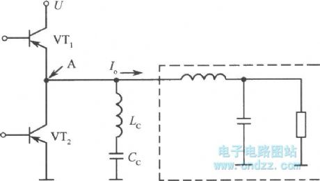
The inductance current commutating mode converter is seldom occuring the phenomenon of surge, even if it adopts non-resonant mode to zero voltage switch in principle. Moreover, it can adjust the voltage by PWM control. The diagram is the basic circuit of this mode. Lc is inductance when changing current. Cc is the capacitor (not for non-resonant use) to cut off DC. Under this mode, VT1 and VT2 will turn on and cut off in turns. Among the turning on and cut-off time, the two switches have cut-off time. In this period of time, the power of inductance LC will charge and discharge to the capacitor between drain-source of VT1 and VT2. It can make A point voltage drop to zero or equal to power supply voltage U before next on-off cycle. So it can reach the zero voltage on-ff condition, at the same time, it also controls the surge current.
(View)
View full Circuit Diagram | Comments | Reading(704)
Single end positive energize converter type converting circuit
Published:2011/11/14 3:30:00 Author:May | Keyword: Single end, positive energize, converter, converting
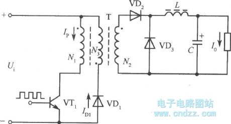
The typical structure of Single end positive energize converter type converting circuit is shown in the diagram. Its circuit form is almost the same as single end negative energize converter. But its working conditions is quite other. When switching transistor VT1 is breaking over, transformer secondary polarity's rectifier diode VD2 is breaking over, and at this time, network is delivering energy to load, and filter inductance L is storing energy; when VT1 is cutting off, inductor continues to release energy to load through fly-wheel diode VD3. It must use clamping winding in single end positive energize converter. The function of clamping winding is to limit the voltage peak on the collector of transistor and make the magnetic flux of high frequency to reset. In general, the turn number of clamping winding is equal to primary winding, and it should close coupling with it. Due to the function of clamping winding, switching transistor VT1's highest back voltage is limiting in two times power supply voltage. At this time, in order to satisfy the condition of magnetic core reset, namely the building time and resetting time of magnetic flux is the same, so the duty factor of this circuit must less than 50%. (View)
View full Circuit Diagram | Comments | Reading(609)
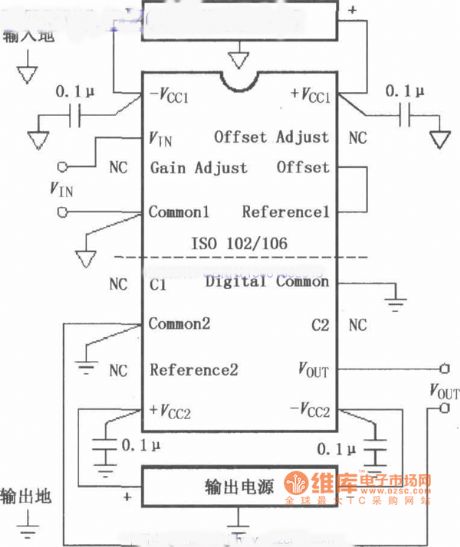
The basic connected circuit of signal of ISO102/106 and power supply
Published:2011/8/30 1:38:00 Author:Jessie | Keyword: connected circuit , signal, power supply
View full Circuit Diagram | Comments | Reading(641)
48V/2A voltage regulator circuit
Published:2011/11/24 0:59:00 Author:May | Keyword: voltage regulator
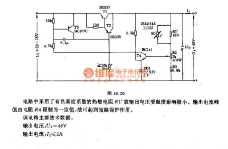
The circuit uses thermistance R1' with negative temperature coefficient, so the temperature has little influence on output voltage. Outrput current peak value is confined to a definite value by resistor R4, so it has the usage of short-circuit protection.
This circuit main technical data:output voltage: U2=48Voutput current: I2≤2Ainput voltage: U1≤40mΩT1 radiator thermal resistance: RthK≤0.63grd/WT2 radiator thermal resistance: RthK≤30grd/Woutput voltage variable quantity:when environmental temperature θU=0~60°C △U2=100mVwhen output current I2=0~2A (U1=constant) : △U2=80mAwhen input voltage U1=52~78V (I2=0) △U2=30mA (View)
View full Circuit Diagram | Comments | Reading(3181)
Multidigit scaling circuit for performance
Published:2011/12/1 1:29:00 Author:May | Keyword: Performance, multidigit scaling
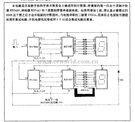
This circuit is the countersuitablefor demonstration teaching and technology exhibition, and it is composed of the counting counter RS7490, encoder RS7447 and seven segment digital tube. If it is added two stage again, display can start new count cycle only when it gets the number of 9999. Diode IN194 connected to battery in series with battery is used to prevent damage integrated circuit from misconnection power polar and reduce power supply boltage to 5V in order to fit the need of intergrated circuit.
(View)
View full Circuit Diagram | Comments | Reading(833)
Thyristor circuit using integrated trigger TD1028
Published:2011/11/10 1:09:00 Author:May | Keyword: Thyristor, integrated trigger
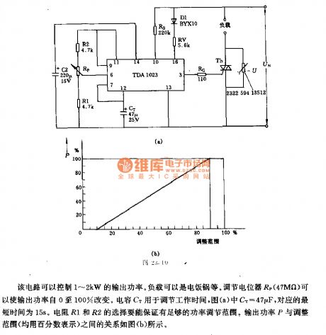
This circuit can control 1~2kW output power. The load can be electric cooker and so on. Adjusting potentiometer Rp (47MΩ) canmake output power change from 0 to 100%. Capacitor Ct isused for adjusting working time, and in diagram (a), cT=47µF, and the corresponding minimum duration is 15s. Resistord R1 and R2 should ensure engough power adjusting range. The relationshipbetween output power P and adjusting range ( all show as percentage) is shown in diagram (b) . (View)
View full Circuit Diagram | Comments | Reading(1100)
74 series digital circuit 74HC564 and other eight D flip-flop (three-state, opposite phase)
Published:2011/11/11 0:43:00 Author:May | Keyword: , eight D flip-flop, three-state, opposite phase


Its function table is the same with 74LS534. (View)
View full Circuit Diagram | Comments | Reading(792)
74 series digital circuit 74LS563 eight D latch (three-state, opposite phase)
Published:2011/11/11 0:43:00 Author:May | Keyword: digital, eight D latch, three-state, opposite phase

Its function table is the same with 74LS533. (View)
View full Circuit Diagram | Comments | Reading(823)
74 Series digital circuit 74LS540/541 and other eight buffer/bus driver (three-state)
Published:2011/11/11 0:42:00 Author:May | Keyword: digital, eight buffer, bus driver, three-state

When either G1 or G2 (or both of them ) is high , all outputs are in high impedance ; when G1 and G2 are in low level, the output is valid. 540 is the inverting output. 541 is the same-phase output.
(View)
View full Circuit Diagram | Comments | Reading(1625)
74 series digital circuit 74LS537 BCD-decimal decoder (Tri-State)
Published:2011/11/11 0:37:00 Author:May | Keyword: 74 series, digital, BCD-decimal decoder, Tri-State

It can do forward output or inverted output switching; It has tri-state output. (View)
View full Circuit Diagram | Comments | Reading(1923)
74 series of digital circuit 74LS534 octal D latch (tri-State, inverting)
Published:2011/11/11 0:33:00 Author:May | Keyword: 74 series, digital, eight D latch, Tri-State, inverting

Q0 = the output level before establishing steady-state input conditions (View)
View full Circuit Diagram | Comments | Reading(1293)
74 series digital circuit 74LS533 octal D latch (Tri-State, inverting)
Published:2011/11/11 0:29:00 Author:May | Keyword: 74 series, digital, octal D latch, Tri-State, inverting

Function and pin diagram are the same with 74LS688 and 74HC688. 74LS533, 74S533, 74F533.74HC533, 74ALS533, 74HCT533 octal D- Latch ( Tri-State , inverting ). 74XX373 is inverting output type. (View)
View full Circuit Diagram | Comments | Reading(1726)
AC voltage controller circuit using unidirectional thyristor
Published:2011/11/30 20:10:00 Author:May | Keyword: AC voltage controller, unidirectional thyristor
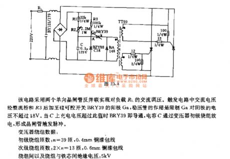
This circuit uses two unidirectional thyristors connectedinversed and in parallel to realize AC voltage adjusting forload RL. Trigger circuit's AC voltage is added to anode Ga of silicon controlled switch BRY39through rectifier bridge and R3,and the voltage regulator tube is used tolimit Ga's voltage oncathode being not more than 18V. When charge voltage on C ismore than this value, BRY39 will be breakover, capaciotr C discharges through transformer's first winding toform thyristor trigger pulse.Transformer winding data:first winding turns: n=39 , 0.4mm copper enameled wiresecondary winding turns: 2×n=13 , 0.6mm copper enameled wireisolation voltage between windings and iron core: 5kV (View)
View full Circuit Diagram | Comments | Reading(2216)
π type filter circuit composed of ISO122/124
Published:2011/11/9 21:53:00 Author:May | Keyword: filter

The diagram is π type filter circuit composed of ISO122/124. ISO122/124 internal osicillator set the modem frequency at 500KHz. In order to suppressthe noise from DC/DC convertor, ituses π type filter composed of inductors and capacitors wave filtering at every power source end. After wave filtering, ISO122/124 output end's 500KHz ripples are suppressed to 20mV, then it uses low-cost OPA602 ( or OPA237) to make up two pole low-pass filter forfurther wave filtering, and the two pole low-pass filter cutoff point is 100KHz.
(View)
View full Circuit Diagram | Comments | Reading(1234)
Digital counting demonstration circuit
Published:2011/10/27 22:47:00 Author:May | Keyword: Digital counting demonstration
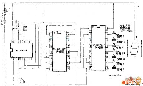
555 timer is used as clock to drive RS7490 decimal system counter, then theBCD output of counter isreturned to 7-segment tube. Ajusting R7 can change the frequency of clock. (View)
View full Circuit Diagram | Comments | Reading(1401)
The circuit of IC decoder on the EPSON ink cartridge
Published:2011/8/30 1:45:00 Author:Jessie | Keyword: IC decoder, EPSON ink cartridge

View full Circuit Diagram | Comments | Reading(3279)
Buick GL8 car ABS wheel speed sensor and ABS electronic control unit circuit
Published:2011/8/24 2:38:00 Author:Jessie | Keyword: Buick GL8 car, ABS wheel, speed sensor, ABS , electronic control unit
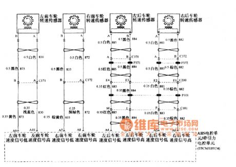
Buick GL8 car ABS wheel speed sensor and ABS electronic control unit traction electronic control unit EBCMEBTCM circuit (View)
View full Circuit Diagram | Comments | Reading(902)
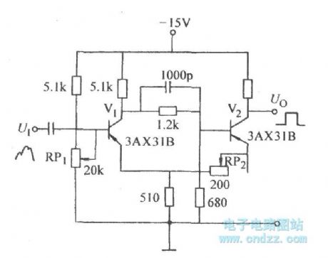
Emitter-coupled bistable circuit for improving sensitivity
Published:2011/10/18 22:00:00 Author:Ecco | Keyword: Emitter-coupled bistable , improving sensitivity
View full Circuit Diagram | Comments | Reading(665)
| Pages:91/471 At 2081828384858687888990919293949596979899100Under 20 |
Circuit Categories
power supply circuit
Amplifier Circuit
Basic Circuit
LED and Light Circuit
Sensor Circuit
Signal Processing
Electrical Equipment Circuit
Control Circuit
Remote Control Circuit
A/D-D/A Converter Circuit
Audio Circuit
Measuring and Test Circuit
Communication Circuit
Computer-Related Circuit
555 Circuit
Automotive Circuit
Repairing Circuit