
Index 86
TV sound infrared repeater circuit
Published:2012/8/21 2:05:00 Author:Ecco | Keyword: TV sound , infrared repeater
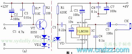
The repeater consists of two parts of the transmitting and receiving. Figure 1 (a) shows the emitting schematic. The frequency discriminator sound ( audio ) signal is amplified by the transistor VT to promote infrared emission tube. Since the emission intensity of the emission tube is proportional to the current, the infrared light emitted by VD1, VD2 is modulated by the audio signal. In order to prevent distortion, VD1, VD2 must set a certain bias. Figure 1 (b) shows the receiving schematic diagram. The circuit uses an audio amplifier IC LM386. VD is the infrared receiver. When the audio signal is irradiated onto VD by modulated infrared light, it will produce the electrical signal which is the same with audio signal on two ends, then it is coupled to IC for amplification by C1.
(View)
View full Circuit Diagram | Comments | Reading(2143)
The automatical switch for TV aural transmitter
Published:2012/8/21 1:43:00 Author:Ecco | Keyword: automatical switch , TV , aural transmitter
The principle: when the TV is turned on, it will generate a strong electromagnetic field around TV, the electromagnetic field is mainly generated by the line scanning system of the television kinescope. TV line scanning frequency is 15.625kHz. So compared to the AC mains, the frequency is higher. As long as detecting the electromagnetic field, it will complete the task by turning on the power switch of broadcast system. In order to make the circuit simple without higher cost, electronic switch for the circuit is served by FET VT. Because the required driving power FET is minimal, it does not need drive current almost. The magnet coil L absorbes to open the TV, then the energy of the electromagnetic field will be generated around the TV.
(View)
View full Circuit Diagram | Comments | Reading(964)
A long-range FM transmitter circuit (500M)
Published:2012/8/21 2:41:00 Author:Ecco | Keyword: long-range , FM , transmitter, 500M
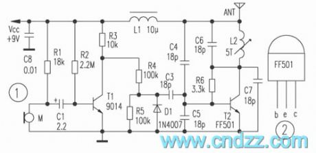
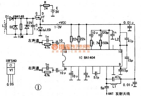
In the circuit shown as Figure 1, the dedicated launch tube T2 and its peripheral components form a high-frequency oscillator with frequency range in 88 ~ 108MHz. The audio signal is picked up by electret microphone and amplified firstly by T1, then the amplified low-frequency signal modulates the high frequency carrier. If the electret microphone M disconnects, the output end connects player to send the music signal. Dedicated tube T2 for RF Transmitter selects FF501 which uses standard T0-92 package ( like the 9000 series of transistors ), and the shape and pin arrangement are shown in Figure 2, and ICM is 45mA, fT is greater than 1.3GHz, VCEO is 13V. The advantages of a dedicated tube include good consistency, greater RF output power, adjustment of circuit, FF501 can fully work in the higher frequency band.
(View)
View full Circuit Diagram | Comments | Reading(3215)
Wireless microphone circuit with NAND gate
Published:2012/8/19 21:17:00 Author:Ecco | Keyword: Wireless microphone, NAND gate
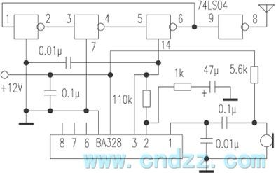
74LS04 is a TTL integrated circuit, there are six single-end input NAND gates. Three NAND gates can form an oscillator. When the power supply voltage is 5V, the oscillation frequency is approximately 90MHz; When supply voltage drops, frequency reduces; when supply voltage rises, frequency increases. Of course, the oscillation amplitude will also change, but has little effect. In this way, people can use the way bu changing the power supply voltage to adjust the frequency ( FM ). The specific approach is to use an audio amplifier IC BA328's output as its power supply. BA328 is a recording head amplifier.
(View)
View full Circuit Diagram | Comments | Reading(1319)
Sensitive photoswitch circuit composed of phototransistor
Published:2012/8/20 0:57:00 Author:Ecco | Keyword: Sensitive photoswitch , phototransistor
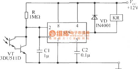
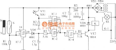
As shown in the figure, the circuit uses Darlington phototransistor sensing elements, so it is more sensitive to low light. It is suited to the detect the reflected light signal. After Darlington photodiodes in the circuit get light, its internal resistance is reduced, so that the potential of pin 2 drops, when it is reduced to (1/3) Vcc, the output of pin 3 is in high level, then the relay releases.
(View)
View full Circuit Diagram | Comments | Reading(1394)
Light trigger switch composed of phototransistor
Published:2012/8/20 1:00:00 Author:Ecco | Keyword: Light , trigger, switch , phototransistor
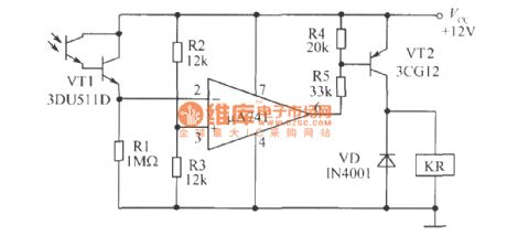
As shown in figure, the circuit uses Darlington phototransistor and op amp, sovery faint light also can make the circuit flip. When R1 and photodiode's positions arereversed, and the op-amp inverting and noninverting input ends are reversed, the circuit can be modified for dark trigger switch.
(View)
View full Circuit Diagram | Comments | Reading(1284)
Light-operated switch circuit
Published:2012/8/19 22:12:00 Author:Ecco | Keyword: Light-operated switch
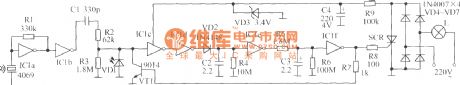
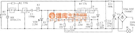
As shown in figure, under normal conditions, the AC voltage passes incandescent, VD4 ~ VD7 bridge rectifier, voltage divider circuit composed of resistor R9 and regulator circuit composed of VD3, C4 to form a loop, the loop current is less than 0.9 mA, power consumption is less than 0.2W, then lights are not bright. When sound sensitive components receive acoustic, acoustic signal is converted into electrical signal, then it passes IC1a, IC1b to make two-stage amplification, and the coupling capacitor C1 will remove the interference signal generated by the low-frequency vibration. When the ambient light is strong, the signal is bypassed by photosensitive diode VD1, and it won't be output for following stage; when the ambient light is weak, VD1 is open, pre- output acoustic signal is amplified by IC1c and 1C1d, VD2, C2, R4 form rectifier and filter circuit to rectify audio signal output by IC1d into a DC signal.
(View)
View full Circuit Diagram | Comments | Reading(867)
Long-range FM radio transmitter circuit
Published:2012/8/19 20:46:00 Author:Ecco | Keyword: Long-range , FM , radio transmitter

In the circuit shown as Figure 1, the special launch tube T2 and its peripheral parts form a high-frequency oscillator with frequency in the range of 88 ~ 108MHz. The electret microphone picks up the audio signal, then the signal is amplified by T1, then the amplified low frequency signal makes modulation for high-frequency carrier. If the electret microphone M disconnects, the input end connects cassette player, and it can transmit music. The RF transmitter dedicated tube T2 chooses FF501 which uses a standard T0-92 package (like the 9000 series of transistors ) , shape, and pin arrangement is shown in Figure 2. The dedicated tube has the advantages of good consistency, the RF output power is greater, and the circuit is easy to adjust, and the FF501 also can work at a higher frequency band.
(View)
View full Circuit Diagram | Comments | Reading(3198)
Power-saving corridor lights circuit
Published:2012/8/19 23:02:00 Author:Ecco | Keyword: Power-saving , corridor lights
It is composed of rectifier circuit (diodes VD4 ~ VD7), buck and filter circuit (R10 and C4), control switch VS on the lights H ( VS gets breakover, H is lit ; VS gets shutdown, the H is turned off), light control circuit ( photodiode VD1, inverters F3 , F4, , F5 and F6 and transistor VT ), voice control circuit ( sound - electrical conversion piezoelectric ceramic BH, inverter, F1 , F2, F3, the F4 , F5, F6 and VD3 , C3, R8) and other components.
(View)
View full Circuit Diagram | Comments | Reading(1152)
Gated light switch circuit composed of phototransistor
Published:2012/8/19 22:44:00 Author:Ecco | Keyword: Gated light , switch , phototransistor
When people go home at night, they need to find the light switch in the dark after opening the door; or go out at night, they need to turn off the lights in the dark after locking the door. These occasions bring some inconvenience. Gated light switch circuit shown as the figure can turn on the indoor lights automatically when you go home to open the door at noght; or when you go outside at night, the corridor lights can be turned on automatically with delay 40s, so the circuit can bring you convenience. Charged lamp is not lit during the day. The whole circuit is composed of gated switch, light control switch, delay circuit, the RS flip-flop, implementation circuit and power circuit.
(View)
View full Circuit Diagram | Comments | Reading(1110)
Ultrashort wave tuner circuit with M0S prestage
Published:2012/8/19 22:01:00 Author:Ecco | Keyword: Ultrashort wave , tuner, M0S prestage
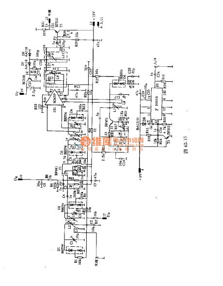
This circuit uses a dual - loop input with band-pass filter to make great prestage selection. It uses MOS prestage and followed ring mixer IC to make high signal intensity. It connects a dual-loop-pass filter between prestage and ring mixer stage in order to achieve good image frequency selection.The main coil data:L1 : o.5mm copper enameled wires with 1 turns;L2, L3, L5:0.8mm copper and silver wires with 5 turns ;L4 : 6 turns , L5 : 5 turns. L4, L5 are 0.8mm copper and silver wires;L6 : 2 turns , L7: 7 turns , L8 : 2 turns , L9 : 12 turns . L6 ~ L9 are 0.5mm copper enameled wires;L9: 12 turns , L10: 2 turns , L11: 12 turns . L9 ~ L11 are copper enameled wires.
(View)
View full Circuit Diagram | Comments | Reading(1042)
Transistors UHF tuner circuit
Published:2012/8/19 21:48:00 Author:Ecco | Keyword: Transistors , UHF, tuner

In the circuit, the adjustable prestage is composed of transistor AF279, and the natural oscillation mixer stage consists of transistor AF280. The power circuit is installed on the board with copper coating. The main coil data:L1, L3, L8, L9: eight turns, the coil uses 0.35mm copper enameled wire with diameter in 3mm;L2 : 3 turns, L10 : 15 turns, L11: 15 turns. L2 , L10, L11 use 0.35mm copper enameled wire with coil diameter in 4.3mm.L12: 5 turns , L13, : 4.5 turns . L12 , L13 use 0.35mm of copper enameled wire with coil diameter in 3.5mm.
(View)
View full Circuit Diagram | Comments | Reading(2716)
Numerical control machine PLC circuit with HK-1 Hall approach switch
Published:2012/8/16 0:56:00 Author:Ecco | Keyword: Numerical control machine , PLC circuit, Hall , approach switch
This circuit can also be used on numerical control machine programmable controller (PLC), andits accuracy is up to 0.02mm; it also canbe used for high - speed punch, material sending and cutting, stroke control of complex pattern mold.
(View)
View full Circuit Diagram | Comments | Reading(847)
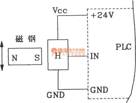
Typical application circuit of two- wire smart Hall sensor IC TLE4941
Published:2012/8/16 0:59:00 Author:Ecco | Keyword: Typical application , two- wire, smart, Hall, sensor IC
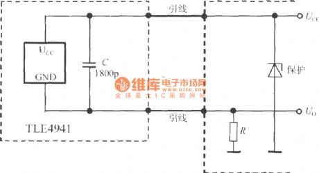
C is the de-noising capacitor. Output currentcan be converted into voltage signal Uo byresistor Rand sent todigital voltmeter (DVM), or microcontroller with ADC.
(View)
View full Circuit Diagram | Comments | Reading(1136)
TDA7274 motor speed stabilizing control integrated circuit diagram
Published:2012/8/16 23:01:00 Author:Ecco | Keyword: motor, speed stabilizing, control, integrated circuit
The TDA7274 is the motor speed stabilizing control integrated circuit produced by a European company, and it is widely used in music players, video machines and electronic toys.(1) Features and functionsTDA7274 IC internal circuit contains reference power supply circuit, error amplification circuit, motor speed control circuit and a number of other subsidiary circuits.(2) Pin functions and dataThe TDA7274 IC uses 8-pin dual in-line package, and the pin functions and data are shown in Table 1.Tip : TDA7274 IC and the domestic model SG7274 can be interchangeable.
(View)
View full Circuit Diagram | Comments | Reading(924)
TDA8177 field scanning output IC diagram
Published:2012/8/16 21:57:00 Author:Ecco | Keyword: field , scanning , output , IC
The TDA8177 is the field scanning output IC produced by French Thomson, which is widely used in a variety of rear-projection color TV at home and abroad, such as the HP clear fine rear projection color TV.
(1) Features and functionsTDA8177 IC 's operating supply voltage range is wider, and the highest supply voltage can be up to 35V, output current can be up to 3A, flyback voltage can be up to 70V. TDA8177 integrated circuit contains the scanning power amplifier, flyback pulse generating circuit, overheating protection and over-current protection circuit, and it is suitable for DC coupling working way.
2 pin functions and dataThe TDA8177 IC uses a separate 7-pin package, and pin functions and data are listed in Table 1.
(View)
View full Circuit Diagram | Comments | Reading(1240)
The counter circuit composed of HK-1 Hall approach switch
Published:2012/8/15 23:10:00 Author:Ecco | Keyword: counter circuit , Hall , approach switch
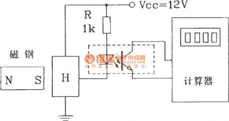
The circuit shown in figure uses optocoupler isolatior and 8 -bit calculator. Whenever the magnet closes to the HK-1 switch once, the calculatorcounts a number and accumulates, thus completing the count function.
(View)
View full Circuit Diagram | Comments | Reading(612)
Binary counter circuit
Published:2012/8/15 23:05:00 Author:Ecco | Keyword: Binary counter
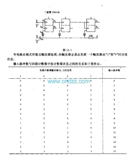
This circuit consists of chained flip flops, and each flip-flop change state when its former trigger changes from 1 to 0. The relationship between the input pulses and each counter status in four counters is shown in the table below.
(View)
View full Circuit Diagram | Comments | Reading(731)
Grating circuit for perforating and sampling
Published:2012/8/16 1:10:00 Author:Ecco | Keyword: Grating circuit , perforating , sampling
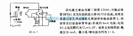
The circuit is mainly composed of the LD261 photodiode, phototransistor BPX81 and following connected amplifier BCY58. If the light is reflected to the phototransistor through the punched tape or bulkhead hole, the pipe and following connected transistor is conduction to form a current which is about 8mA, and voltage Ua on resistor R3 is about 3.2V. If there is no light irradiation, the current is only 1mA. The maximum bright, dark current ratio is about 1:8.
(View)
View full Circuit Diagram | Comments | Reading(657)
The interface circuit between single-chip accelerometer MMA1220D and microcontroller
Published:2012/8/15 21:27:00 Author:Ecco | Keyword: interface circuit , single-chip accelerometer , microcontroller
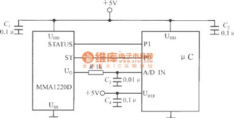
The microcontroller within A / D converter can use PIC MCU within A / D converter produced by the Microchip. MMA1220D's state end and self-test end are connected to the P1, P0 ports of μC, its output voltage is sent to the A / D converter input end. C1, C2 are the power supply decoupling capacitors. A / D converter's reference voltage side ( UREF ) is connected to +5 V power supply.
(View)
View full Circuit Diagram | Comments | Reading(1413)
| Pages:86/471 At 2081828384858687888990919293949596979899100Under 20 |
Circuit Categories
power supply circuit
Amplifier Circuit
Basic Circuit
LED and Light Circuit
Sensor Circuit
Signal Processing
Electrical Equipment Circuit
Control Circuit
Remote Control Circuit
A/D-D/A Converter Circuit
Audio Circuit
Measuring and Test Circuit
Communication Circuit
Computer-Related Circuit
555 Circuit
Automotive Circuit
Repairing Circuit