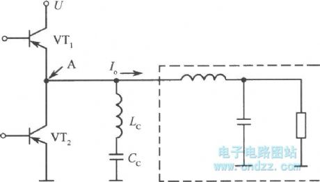
Basic Circuit
Non-resonance converter circuit
Published:2011/11/14 1:08:00 Author:May | Keyword: Non-resonance, converter | From:SeekIC

The inductance current commutating mode converter is seldom occuring the phenomenon of surge, even if it adopts non-resonant mode to zero voltage switch in principle. Moreover, it can adjust the voltage by PWM control. The diagram is the basic circuit of this mode. Lc is inductance when changing current. Cc is the capacitor (not for non-resonant use) to cut off DC. Under this mode, VT1 and VT2 will turn on and cut off in turns. Among the turning on and cut-off time, the two switches have cut-off time. In this period of time, the power of inductance LC will charge and discharge to the capacitor between drain-source of VT1 and VT2. It can make A point voltage drop to zero or equal to power supply voltage U before next on-off cycle. So it can reach the zero voltage on-ff condition, at the same time, it also controls the surge current.
Reprinted Url Of This Article:
http://www.seekic.com/circuit_diagram/Basic_Circuit/Non_resonance_converter_circuit.html
Print this Page | Comments | Reading(3)

Article Categories
power supply circuit
Amplifier Circuit
Basic Circuit
LED and Light Circuit
Sensor Circuit
Signal Processing
Electrical Equipment Circuit
Control Circuit
Remote Control Circuit
A/D-D/A Converter Circuit
Audio Circuit
Measuring and Test Circuit
Communication Circuit
Computer-Related Circuit
555 Circuit
Automotive Circuit
Repairing Circuit
Code: