Basic Circuit
Single end positive energize converter type converting circuit
Published:2011/11/14 3:30:00 Author:May | Keyword: Single end, positive energize, converter, converting | From:SeekIC
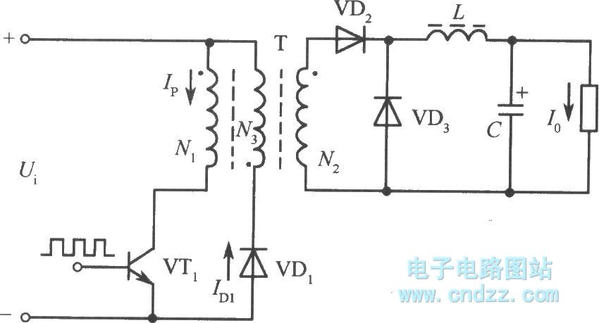
The typical structure of Single end positive energize converter type converting circuit is shown in the diagram. Its circuit form is almost the same as single end negative energize converter. But its working conditions is quite other. When switching transistor VT1 is breaking over, transformer secondary polarity's rectifier diode VD2 is breaking over, and at this time, network is delivering energy to load, and filter inductance L is storing energy; when VT1 is cutting off, inductor continues to release energy to load through fly-wheel diode VD3. It must use clamping winding in single end positive energize converter. The function of clamping winding is to limit the voltage peak on the collector of transistor and make the magnetic flux of high frequency to reset. In general, the turn number of clamping winding is equal to primary winding, and it should close coupling with it. Due to the function of clamping winding, switching transistor VT1's highest back voltage is limiting in two times power supply voltage. At this time, in order to satisfy the condition of magnetic core reset, namely the building time and resetting time of magnetic flux is the same, so the duty factor of this circuit must less than 50%.
Reprinted Url Of This Article:
http://www.seekic.com/circuit_diagram/Basic_Circuit/Single_end_positive_energize_converter_type_converting_circuit.html
Print this Page | Comments | Reading(3)

Article Categories
power supply circuit
Amplifier Circuit
Basic Circuit
LED and Light Circuit
Sensor Circuit
Signal Processing
Electrical Equipment Circuit
Control Circuit
Remote Control Circuit
A/D-D/A Converter Circuit
Audio Circuit
Measuring and Test Circuit
Communication Circuit
Computer-Related Circuit
555 Circuit
Automotive Circuit
Repairing Circuit
Code: