
Index 168
BIPOLAR_ZENER
Published:2009/7/13 21:42:00 Author:May
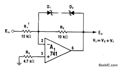
Circuit limits opamp output swing in either direction to sum of zener- and forward.breakdown voltages of D1 and D2. With matched zeners, positive and negative limiting levels are symmetrical. With 10-V zenets, limiting occurs at 10.6 V (10.0 + 0.6 V) to allow linear t 10 V swing without saturating A1. R2 is selected according to gain requirement. Diodes are matched pair chosen to provide desired limit voltage, such as 1N758 for ±10 V output swing.-W. G. Jung, IC 0p-Amp Cookbook, Howard W. Sams, Indianapolis, IN, 1974, p 201. (View)
View full Circuit Diagram | Comments | Reading(1220)
12_V_CROWBAR
Published:2009/7/13 21:39:00 Author:May
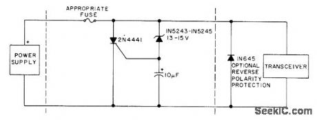
Uses overvoltage-sensing zener to trigger SCR and place it across power supply line, blowing fuse within microseconds to protect transceiver. Optional diode provides protection from accidental reversal of supply polarity.-Circuits, 73 Magazine, July 1977, p 35. (View)
View full Circuit Diagram | Comments | Reading(700)
AUTO_GUARDIAN_RECEIVER
Published:2009/7/13 21:38:00 Author:May
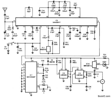
The decoder IC7 cheeks the incoming pulse train for the correct address. If that address is present, the valid output terminal, pin 11, goes high for the 2 1/2-s duration of the transmitted pulse trains. When the valid output signal returns to a low state, timer lC8 is triggered into operation. The output terminal of IC8, pin 3, goes high for a time period of about 11 s, as determined by R22 and C35. That output, in turn, enables IC9, a timer configured as a 50-percent duty-cycle oscillator with a period of about 1/4 s. The output of IC9 drives a piezo buzzer, which produces an attention-getting audio signal that alerts the user that a door of the vehicle has been opened. Power to operate the receiver is obtained from a set of three AAA alkaline cells connected in series to produce 4.5 V. Current draw is only 3 mA during standby, so battery life will be in the hundreds of hours. IC10 is a voltage-detector IC that allows current to flow through LED2 when the battery voltage falls below 3 V. That alerts the user that battery replacement is necessary. (View)
View full Circuit Diagram | Comments | Reading(631)
PLL_WITH_DIVIDE_BY_N_CIRCUIT
Published:2009/7/13 21:37:00 Author:May
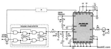
The MAX038 function generator IC can be used in a PLL system. To gain the advantages of a wider capture range and an optional divide-by-N circuit (which allows the PLL to lock onto arbitrary multiples of the applied frequency), you can introduce an external frequency-phase detector, such as the 74HC4046 or the discrete-gate version shown. Unlike phase detectors, which can lock to harmonics of the applied signal, the frequency-phase detector locks only to the fundamental. In the absence of an applied frequency, its output assumes a positive dc voltage (logic 1) that drives the RF output to the lower end of its range as determined by resistors R4 to R6. These resistors also determine the frequency range over which the PLL can achieve lock. Again, R4 to R6, C4, and RZ, determine the PLL's dynamic performance. (View)
View full Circuit Diagram | Comments | Reading(2909)
31_m_SW_CONVERTER_FOR_AUTO_RADIOS
Published:2009/7/13 21:37:00 Author:May
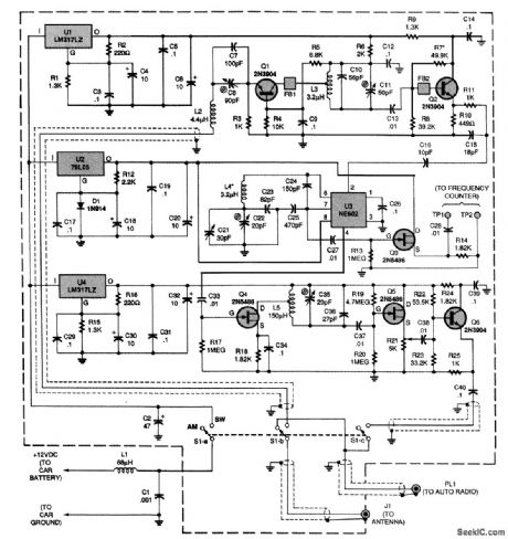
Power for the circuit is taken from the car battery and is dropped to the proper voltages for three sections of the circuit by three separate regulator ICs: U1, U2, and U4. Inductor L2 and capacitors C7 and C8 act as the circuit's antenna tuner. The tuned signal is fed to an input bandpass filter composed of L3, C10, and C11. An NE602 oscillator IC, U3, is used as a combined mixer and oscillator.That configuration is known as a series-tuned CoLpitts or Clctpp osciLlcttor, and is among the most temperature-stable variable oscillators. The 1710-kHz output filter consists of L5, C35, and C36.Each of the filters in the circuit was limited to a single LC section to simplify as much as possible the alignment of the converter. Transistor Q3 is a frequency-counter buffer that is used only during alignment. The gain of the converter is sufficient to overload the input of some receivers. Poten-tiometer R21 can be used to decrease the output level and prevent overload. (View)
View full Circuit Diagram | Comments | Reading(860)
OPAMP_AS_CLIPPER
Published:2009/7/13 21:37:00 Author:May

Two zeners are used to clip both sides of AC signal. Clipping level is determined by rating of zeners used, which can be 6, 9, 12, or 15V depending on application. Ratio of R2 to R1 determines amplification. If long supply leads cause oscillation, connect 0.1-μF capacitors between ground and suρply ρins 4 and 7 as shown.-F.M. Mims,''Integrated Circult Proiects,Vol. 4,″Radio Shack,Fort Worth,TX,1977,2nd Ed,p 37-44. (View)
View full Circuit Diagram | Comments | Reading(1479)
TUNNEL_DIODE_GATE
Published:2009/7/16 2:25:00 Author:Jessie
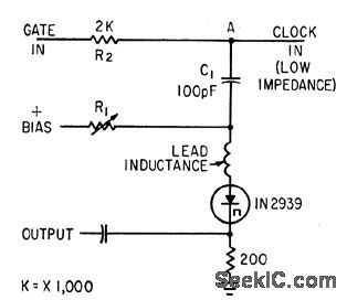
Impedance of tunnel diode is part of voltage divider, eliminating mood for a-c bridge in gate operating above 500 Mc.-F. W. Kantor, Tunnel-Diode Gate has Subnanosecond Rise Time, Electronics, 35:15, p 62-64. (View)
View full Circuit Diagram | Comments | Reading(664)
BASIC_NOR_GATE
Published:2009/7/16 2:25:00 Author:Jessie
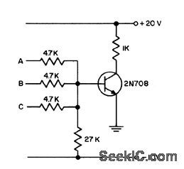
Transistor conducts heavily if any of inputs is raised from 0 to +12 V.- Transistor Mcnual, Seventh Edition, General Electric Co., 1964, p 178. (View)
View full Circuit Diagram | Comments | Reading(518)
FET_ANALOG_GATE
Published:2009/7/16 2:24:00 Author:Jessie

Series connection of chopper-type fet permits high-accuracy analog switching. Resistance of Q2 when on is only about 20 ohms, and drain gate leakage current is less than 0.1 nanoamp.-Six More Semiconductor Advances From TI (Texas Instruments ad), EEE, 14:8, p 120-121. (View)
View full Circuit Diagram | Comments | Reading(659)
RF_METER
Published:2009/7/16 2:24:00 Author:Jessie
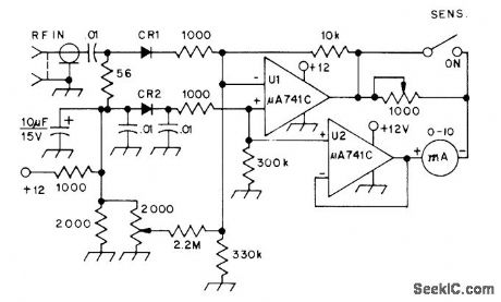
Simple square-law detector can detect and measure signals as low as -26 dBm, at microwatt levels. CR1 is biased with about 20 μA by opampU1 serving as low-impedance DC source. CR2 provides temperature compensation, and U2 serves as low-impedance reference for 10-mA meter. Diodes can be hot-carrier types or 1N914s.-W. Hayward, Defining and Measuring Receiver Dynamic Range, QST, July 1975, p 15-21 and 43. (View)
View full Circuit Diagram | Comments | Reading(1054)
POSITIVE_TRANSMISSION_GATE
Published:2009/7/16 2:23:00 Author:Jessie
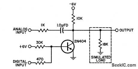
Is equivalent to digitally controlled analog switch, for frequency range of 8 to 650 kc. Output signal never passes through active device, hence is not attenuated, distorted, or delayed. Will pass a-c signal with zero aver age value. Ratio of on voltage to off voltage is 420:1 (4.2 V pp to 10 mV p-p), for isolation of 54.5 db.-V. A. Bloom, Positive Transmission Gate, EEE,10;9, p 26-27. (View)
View full Circuit Diagram | Comments | Reading(572)
FAST_READOUT_MEMORY
Published:2009/7/16 2:22:00 Author:Jessie
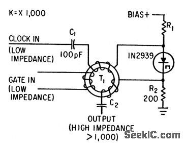
Voltage-divider version of tunnel-diode gate is used with toroid to give extremely fast readout, for use with computers having dock rates above 500 Mc. Tertiary winding cancels gating spike.-F. W. Kantor, Tunnel-Diode Gate has Subnanosecond Rise Time, Electronics, 35:15, p 62-64. (View)
View full Circuit Diagram | Comments | Reading(587)
NPN_NOR_GATE
Published:2009/7/16 2:22:00 Author:Jessie
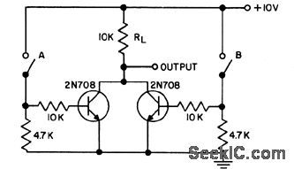
Circuit is or gate if dosing of switch is an input. Circuit is and gate if opening of switch is an input. Provides phase inversion of input. If both switches are open, both transistors are nonconducting. When either switch is dosed, output is negative, or not or, because of phase inversion, and circuit is therefore nor gate.- Transistor Manual, Seventh Edition, General Electric Co., 1964, p 176. (View)
View full Circuit Diagram | Comments | Reading(614)
GATE_WITH_TAPPED_TOROID
Published:2009/7/16 2:21:00 Author:Jessie

Arrangement of toroid windings minimizes number of com ponents in ac bridge used as computer gate, while keeping gating pulse out of output.R3 adjusts balance. Bias is adjusted for stable switching.-F. W. Kantor, Tunnel-Diode Gate has Subnanosecond Rise Time, Electronics, 35:15, p 62-64. (View)
View full Circuit Diagram | Comments | Reading(616)
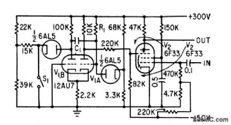
PHANTASTRON
Published:2009/7/16 2:21:00 Author:Jessie
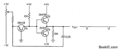
Reversal of current and volt-age functions of basic three-transistor phantastron sweep generator results in pulse output that is derivative of sawtooth sweep.-N. C. Hekimian, Phantastron Circuits Using Transistors, Electronics, 34:8, p 46-47. (View)
View full Circuit Diagram | Comments | Reading(2161)
TRIPLING_TO_12672_MHz
Published:2009/7/13 21:36:00 Author:May
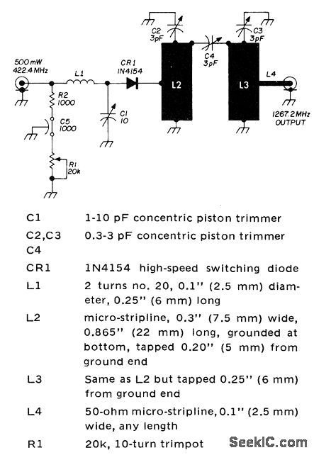
Diode tripler and filter combination is designed for double-clad glass epoxy printed-circuit board to simplify construction. Developed for use in 1296-MHz SSB transceiver for amateur 23-cm band. RF energy from 422.4-MHz power amplifier is applied to GE 1N4154 high-speed switching diode through L network .Harmonic comb at output of diode passes only desired frequency to output terminal going to mixer of transceiver. -H. P. Shuch, Easy-to-Build SSB Transceiver for 1296 HMz, Ham Radio, Sept. 1974, p 8-23. (View)
View full Circuit Diagram | Comments | Reading(637)
INFRARED_CURTAIN_BIRD_COUNTER
Published:2009/7/13 21:36:00 Author:May
System registers appearance of bats and other moving objects moving through curtain of infrared light. Logic circuit determines direction of travel. Direction and pass time are automatically printed by mechanical register K1.-P. A. Tove and J. Czekajewski, infrared Curtain System Detects and Counts Moving Objects, Electronics, 34:31, p 40-43. (View)
View full Circuit Diagram | Comments | Reading(623)
BENCHTOP_FUNCTION_GENERATOR_WITH_BUILT_IN_COUNTER_
Published:2009/7/13 21:36:00 Author:May
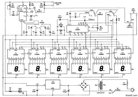
This circuit will produce sine, square, and triangle waves from 0.1 Hz to 1 MHz and has a counter which will read the frequency of the function generator or an external signal of a few volts peak-to-peak that will drive the CMOS counter. (View)
View full Circuit Diagram | Comments | Reading(3256)
NE602_FREQUENCY_CONVERTER
Published:2009/7/13 21:32:00 Author:May
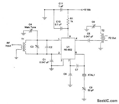


The NE602 can be used as a frequency converter with this circuit.
(View)
View full Circuit Diagram | Comments | Reading(2347)
NE602_DIRECT_CONVERSION_OUTPUT_CIRCUIT
Published:2009/7/13 21:30:00 Author:May
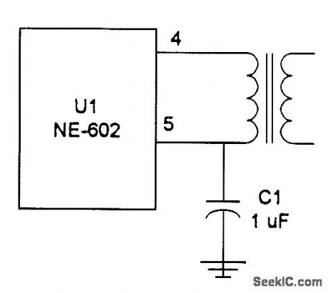
This figure shows a direct-conversion output circuit for an NE602. (View)
View full Circuit Diagram | Comments | Reading(526)
| Pages:168/471 At 20161162163164165166167168169170171172173174175176177178179180Under 20 |
Circuit Categories
power supply circuit
Amplifier Circuit
Basic Circuit
LED and Light Circuit
Sensor Circuit
Signal Processing
Electrical Equipment Circuit
Control Circuit
Remote Control Circuit
A/D-D/A Converter Circuit
Audio Circuit
Measuring and Test Circuit
Communication Circuit
Computer-Related Circuit
555 Circuit
Automotive Circuit
Repairing Circuit