Basic Circuit
AUTO_GUARDIAN_RECEIVER
Published:2009/7/13 21:38:00 Author:May | From:SeekIC

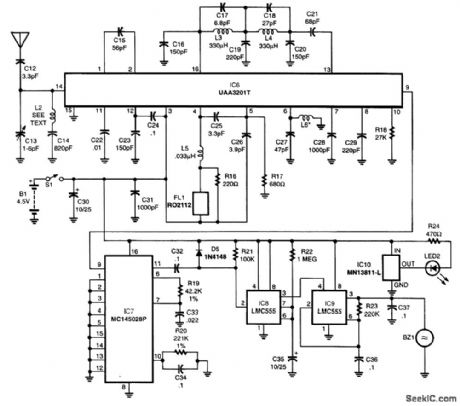
The decoder IC7 cheeks the incoming pulse train for the correct address. If that address is present, the valid output terminal, pin 11, goes high for the 2 1/2-s duration of the transmitted pulse trains. When the valid output signal returns to a low state, timer lC8 is triggered into operation. The output terminal of IC8, pin 3, goes high for a time period of about 11 s, as determined by R22 and C35. That output, in turn, enables IC9, a timer configured as a 50-percent duty-cycle oscillator with a period of about 1/4 s. The output of IC9 drives a piezo buzzer, which produces an attention-getting audio signal that alerts the user that a door of the vehicle has been opened. Power to operate the receiver is obtained from a set of three AAA alkaline cells connected in series to produce 4.5 V. Current draw is only 3 mA during standby, so battery life will be in the hundreds of hours. IC10 is a voltage-detector IC that allows current to flow through LED2 when the battery voltage falls below 3 V. That alerts the user that battery replacement is necessary.
Reprinted Url Of This Article:
http://www.seekic.com/circuit_diagram/Basic_Circuit/AUTO_GUARDIAN_RECEIVER.html
Print this Page | Comments | Reading(3)

Article Categories
power supply circuit
Amplifier Circuit
Basic Circuit
LED and Light Circuit
Sensor Circuit
Signal Processing
Electrical Equipment Circuit
Control Circuit
Remote Control Circuit
A/D-D/A Converter Circuit
Audio Circuit
Measuring and Test Circuit
Communication Circuit
Computer-Related Circuit
555 Circuit
Automotive Circuit
Repairing Circuit
Code: