
Index 158
2_W_FOR_20_METER_CW
Published:2009/7/14 2:29:00 Author:May
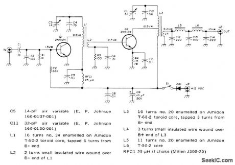
Motorola 2N4124 driver operates as class B amplifier. With no signal, collector current is near zero, minimizing current drain when key is up. Tank circuit of RCA 2N5189 final is similar to that of driver. Double-pi network in output assures good harmonic attenuation. RMS values of BF voltages are marked with asterisks. Protective diode CR1 is any silicon rectifier. For portable use, supply can be lantern battery.-C. E. Galbreath, Low Power Solid-State VFO Transmitter for 20 Meters, Ham Radio, Nov. 1973, p 6-11. (View)
View full Circuit Diagram | Comments | Reading(1531)
DIFFERENTIAL_DISCRIMINATOR
Published:2009/7/15 21:05:00 Author:Jessie
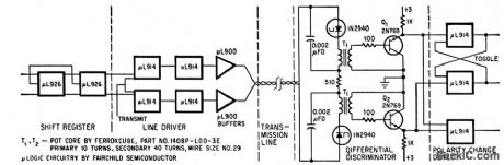
Tunnel diodes serve as current level detectors, allowing detection of serial bit information while providing common-mode rejection of noise. Used in system for transmitting phase-moduulated digital data over telephone line. Original pulse waveforms are restored by diodes.-F. Salter, Differential Discriminator Rejects Common-Mode Noise.Electronics.39:15,p101-102. (View)
View full Circuit Diagram | Comments | Reading(451)
CCTV_DISPLAYS_VOLTAGES_AS_VOLTAGES_BAR_GRAPHS
Published:2009/7/15 21:25:00 Author:Jessie
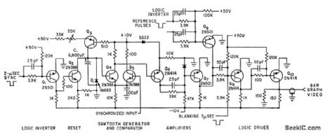
No change is necessary in closed-circuit television monitor. Switch gives choice of bar graph or picture display. Horizontal lines can be electronically positioned on screen as go and no go limits. Display con version system has counter that commutates up to 20 low-frequency analog voltages on to common bus feeding comparator input shown.-D. Cohen. Converter Produces Television Bar Display. Electronics.34:44,p45-47. (View)
View full Circuit Diagram | Comments | Reading(731)
BIDIRECTIONAL_ACTIVE_LOAD
Published:2009/7/15 23:13:00 Author:Jessie
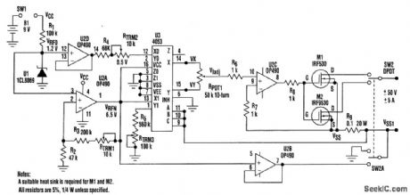
The design presented here is a single +9-V, battery-operated, bidirectional active load that can sink and source current. This is a low-power design, consuming only about 140μA. The power MOSFET selected (IRF530 N-channel and IRF9530 P-channel), after derating, accepts a maximum load of ±50V at ±5 A. The key to the design is having two different sets of voltage levels at Vx ,VY, and VSS1. One set is for current-sinking test, while the other is for current-sourcing test. (View)
View full Circuit Diagram | Comments | Reading(3423)
CONSTANT_PULSE_WIDTH__ONE_SHOT
Published:2009/7/15 23:12:00 Author:Jessie
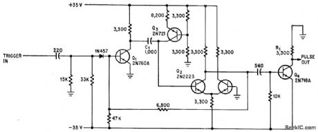
Monostable circuit holds pulse width constant within 0.5% from -65℃. Stages Q1 and Q2 form conventional one-shot. Use of differential amplifier for Q2 stabilizes base voltage for turn-on of Q2 near ground. Constant-current transistor Q3 minimizes effects of small voltage variations, and switching transistor Q4 provides 35-V output pulse with base line at ground.-R. Stevens, One-Shot Multi Produces Constant Pulse Width, Electronics, 34:13, p 74-75. (View)
View full Circuit Diagram | Comments | Reading(900)
MOBILE_DISCRIMINATOR_AND_LIMITER
Published:2009/7/15 23:11:00 Author:Jessie
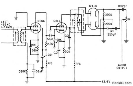
Two limiter stages in cascade precede Foster-Seely discriminator.-C. Gonzalez and R. J. Nelson, Design of Mobile Receivers with Low-Plate-Potential lubes, Electronics, 33:34, p 62-65. (View)
View full Circuit Diagram | Comments | Reading(661)
6_METER_PREAMP
Published:2009/7/15 23:01:00 Author:Jessie

Simple transistor circuit requires no tuning, draws less than 50mW from 9-V supply, and increases sensitivity of low-priced receiver without complicated impedance matching.-E. R. Davisson, Simple Six Pre-Amp, 73Magazine, Oct. 1974, p 111-112. (View)
View full Circuit Diagram | Comments | Reading(1131)
TRANSIENT_DETECTOR
Published:2009/7/15 23:00:00 Author:Jessie
Transient or other pulse at input turns on scr Q1, pulling in dpdt latching relay. Q2 then charges C through R2 until emitter voltage of Q2 is high enough to make it conduct and provide trigger pulse for Q3 to unlatch relay.-D. P. Lynch, Unijunction Transistor Tums off latching Relay, Electronics, 38:23, p 109. (View)
View full Circuit Diagram | Comments | Reading(1262)
RECEIVER_CHECKING_VFO
Published:2009/7/15 23:00:00 Author:Jessie
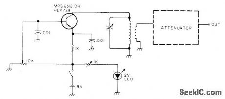
Simple variable-frequency oscillator is combined with attenuator network to generate signal of about 1 μV for checking performance of amateur radio receiver quickly. Attenuator is series arrangement of 47-, 100-, 100-, and 47-ohm resistors, with 1-ohm resistors going from each of the three junctions to ground. LC combinations are chosen for amateur band desired. Circuit will work down to at least 2 meters.-Is It the Band or My Receiver? , 73 Magazine, Oct. 1976, p 132-133.
(View)
View full Circuit Diagram | Comments | Reading(701)
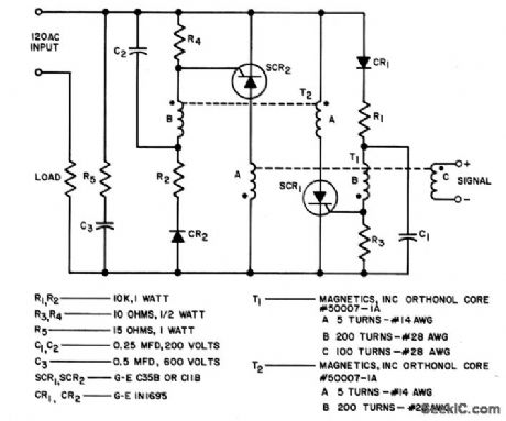
SCR_A_C_LATCHING_RELAY
Published:2009/7/15 22:59:00 Author:Jessie
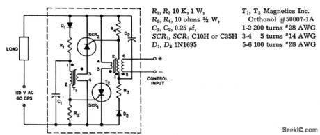
Relay is activated by d-c or a-c control current in single electrically isolated control winding. Can switch load power up to 1.7 kw. Uses magnetic firing circuit in which saturable core is not required to sustain gale voltage for full half-cycle, thereby permitting use of smaller core. Load current must be above 1 amp for conduction to be maintained.-Solid State Latching Relay, Electronic Circuit Design Handbook, Mactier Pub. Corp., N.Y., 1965, p 226. (View)
View full Circuit Diagram | Comments | Reading(934)
POSITIVE_GATING_OF_CLOCK_PULSES
Published:2009/7/15 22:56:00 Author:Jessie
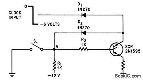
Adding scr latch to diode gate allows output to follow dock input when S1 is dosed. When S1 is open, output will be fixed at existing dock level, without putting extra count into register.-R. A. Wilson, Latching Gate Removes Counter Ambiguity, Electronics, 39:7, p 91-92. (View)
View full Circuit Diagram | Comments | Reading(566)
STEPPER_RELAY_RESET_AND_LATCH
Published:2009/7/15 22:55:00 Author:Jessie
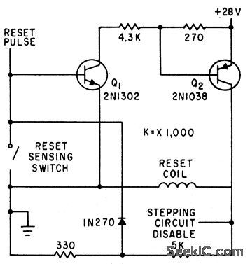
Reset circuit deenergizes lip-lop that controls coils of stepper relay, and provides latching to keep reset coil energized until wiper senses reset contact.-F. W. Kear, Coils Operate Stepping Relay at Higher Speed, Electronics, 35:6, p 60-63. (View)
View full Circuit Diagram | Comments | Reading(1327)
NEON_PHOTOCONDUCTOR_LATCHING_CIR_CUIT
Published:2009/7/15 22:54:00 Author:Jessie
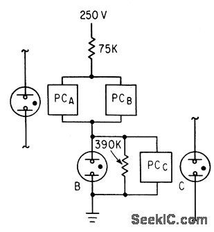
Cadmium sulfide photoconductor PC and Ne2H neon lamps give low-cost latch.When neon C is energized to provide input to PCA, neon B remains on, independent of input A, due to feedback from neon B to PCB. latch is reset by input to PCC.-J. L. Paterson, Will Neon Photoconductors Replace Relays in Low-Speed Logic?, Electronics, 36:18, p 46-49. (View)
View full Circuit Diagram | Comments | Reading(639)
PHOTOELECTRIC_LATCHING_RELAY
Published:2009/7/15 22:53:00 Author:Jessie
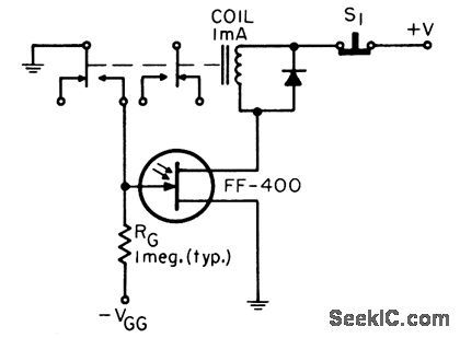
Photo-sensitive let serves as relay in light-activated smoke detectors, end-of-tape sensing in tape recorders, and light-activated alarms.-B. R. Smith, tight-Activated latching Relay, EEE, 14;8, p 167. (View)
View full Circuit Diagram | Comments | Reading(552)
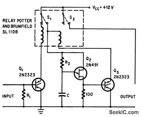
TRANSISTORS_DRIVE_RELAY
Published:2009/7/15 22:52:00 Author:Jessie
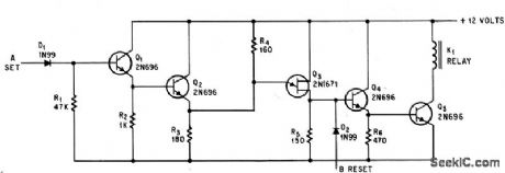
Relay latches on with +12 v set pulse ot A, and is unlatched by +12 v reset pulse at B.-S.E. Summer,Unijunction Tuansistor Latches Relay With Short Pulses,Electronics,38:9,p62.
(View)
View full Circuit Diagram | Comments | Reading(694)
A_C_STATIC_LATCHING_RELAY
Published:2009/7/15 22:50:00 Author:Jessie
Is equivalent to single-pole electromechanical latching relay with electrically isolated solenoid. Once turned on, circuit remains in conducting state even though line voltage is interrupted for long periods of time. Positive reset action requires that minimum load current of 1 amp flow whenever circuit is closed.- Silicon Con-trolled Rectifier Manual, Third Edition, General Electric Co., 1964, p 106. (View)
View full Circuit Diagram | Comments | Reading(689)
THREE_PHASE_OUTPUT_SIAGE
Published:2009/7/15 22:47:00 Author:Jessie
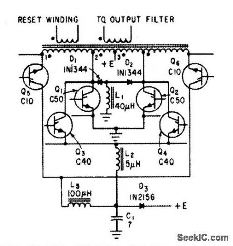
Scr's provide power switching for static inverter designed to develop 500 w of three-phase 115-v 400-cps power from input of 22 to 29 v d-c.-R. J. Kearns and J. J. Rolfe, Three-Phase Static Inverters Power Space-Vehicle Equipment, Electronics, 34:18, p 70-73. (View)
View full Circuit Diagram | Comments | Reading(824)
DUAL_TRIODE_DIFFERENIIAL_INVERTER
Published:2009/7/15 22:46:00 Author:Jessie
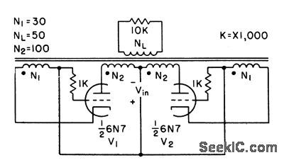
Uses electron tubes as switching elements in place of transistors. Although tubes are less efficient, availability of a suitable combination of voltage rating, current rating, and high-speed switching capacity may make tubes better than transistors in some signal or power converter applications.-C. H. R. Campling, Magnetic Inverter Uses tubes or Transistors, Electronics, 31:11, p 158-161. (View)
View full Circuit Diagram | Comments | Reading(481)
DIFFERENTIAL_MVBR_INVERTER
Published:2009/7/15 22:45:00 Author:Jessie
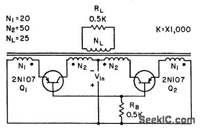
Magnetic inverter circuit with differentially connected windings oscillates reliably without use of current bias. Small spike in square-wave output can be eliminated by connecting small capacitor between collector and emitter of each transistor.-C. H. R. Campling, Magnetic Inverter Uses Tubes or Transistors, Electronics, 31;11, p 158-16l. (View)
View full Circuit Diagram | Comments | Reading(615)
INVERTER_AND_PULSE_STRETCHER
Published:2009/7/14 2:41:00 Author:May

Circuit likes sampled output of multiplexer and provides current required for driving transfluxor in analog-digital converter that produces six-bit binary Gray code.-N. Aron and C. Granger, Analog-To-Digital Converter Uses Transfluxors, Electronics, 35:20,p 62-66. (View)
View full Circuit Diagram | Comments | Reading(1577)
| Pages:158/471 At 20141142143144145146147148149150151152153154155156157158159160Under 20 |
Circuit Categories
power supply circuit
Amplifier Circuit
Basic Circuit
LED and Light Circuit
Sensor Circuit
Signal Processing
Electrical Equipment Circuit
Control Circuit
Remote Control Circuit
A/D-D/A Converter Circuit
Audio Circuit
Measuring and Test Circuit
Communication Circuit
Computer-Related Circuit
555 Circuit
Automotive Circuit
Repairing Circuit