
Index 151
DIFFERENTIAL_LOGARITHM
Published:2009/7/14 4:02:00 Author:May
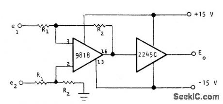
Optical Electronics 9818 opamp and 2245C logamp together give logarithm of differential input voltage or current. Combined transfer function is E0 = K log (R2 /R1 ) (e2- e1). R1 can be zero for differential input current circuit. For unity-gain preamp, R1 and R2 should be 10K. For 1-V full-scale Input, use 10K for R1 and 100K for R2, For l00-mV fullscale input, use 10K for R1 and 1 megohm for R2.- How to Obtain a Differential Logarithm, Optical Electronics, Tucson, AZ, Application Tip 10126. (View)
View full Circuit Diagram | Comments | Reading(579)
TRIODE_MAGNETOSTRICTION_BANDPASS_FIL_TER
Published:2009/7/14 4:02:00 Author:May

Practical range is from 45 to 300 kc. When filler is used with triode, it serves as stable fixed-frequency oscillator in telemetry command receiver.-E. J. Neville, Jr., Designing Magnetostriction Filters, Electronics, 33:51, p 88-89. (View)
View full Circuit Diagram | Comments | Reading(770)
325_KC_BRIDGED_T_FILTER
Published:2009/7/14 4:02:00 Author:May

Used in magnetometer having large amounts of odd harmonics and only feeble second harmonk at secondary of sensing probe. Permits ampli-flying only second harmonic, without excessive phase shift.-F. Voelker, Magnetometer Makes Continuous Measurements, Electronics, 31:11, p 152-154. (View)
View full Circuit Diagram | Comments | Reading(611)
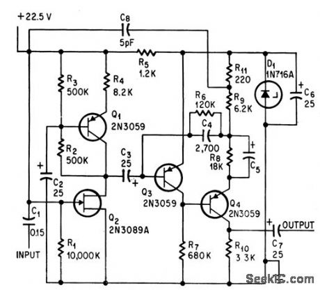
2_30_MHz_SSB_DRIVER
Published:2009/7/14 4:02:00 Author:May
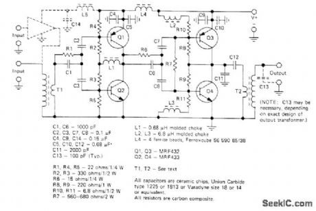
Two-stage complementary-symmetry amplifier combines single-ended impedance matching with high-gain push-pull design to provide up to 25 W PEP for driver applications. Provides good harmonic rejection and low intermodulation distortion. Supply voltage range is 22-30 V. Low-impedance windings of T1 and T2 use 1 turn of copper braid, with 2 turns No. 22 for primary of T1 and 4 turns No. 22 for secondary of T2.-H. Granberg, A Complementary Symmetry Amplifier for 2-30 MHz SSB Driver Applications, Motorola, Phoenix, AZ, 1975, EB-32. (View)
View full Circuit Diagram | Comments | Reading(773)
LOW_PASS_SUBAUDIO_FILTER
Published:2009/7/14 4:01:00 Author:May

Gives flat frequency response from d-c to 1-cps cutoff, attenuation slope of 15 db per octave, near zero insertion loss, and good temperature stability.-R. C. Onstad, Low-Pass Filter for Subaudio Frequencies, Electronics, 33:3, p 88-90. (View)
View full Circuit Diagram | Comments | Reading(692)
ZOBEL_LOW_PASS_FILTER
Published:2009/7/14 4:01:00 Author:May

Amide gives design procedure using Caver parameters. Both examples give 40 db attenuation at 5,000 cps when inserted between 600-ohm source and load resistances.-K. Lichtenfeld, Method for Simplifying Filter Design, Electronics, 33:21, p 96-99. (View)
View full Circuit Diagram | Comments | Reading(819)
0_TO__63_V_AT_1_A
Published:2009/7/14 4:00:00 Author:May
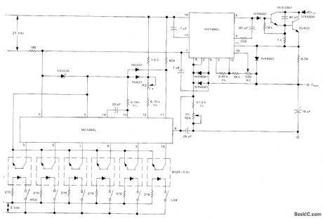
High-voltage digitally controlled power supply uses Motorola MC1406L 6-bit DAC and MC1466L floating voltage regulator to deliver up to 1 A of load current over output voltage that can be incremented in 63 steps of 1 V each, Digital word that controls voltage is coupled into DAC with 4N28 optoisolators. Current-amplifier output stage using Darlington connection of transistors is designed to operate from +70 V supply. -D. Aidridge and N. Wellenstein, Designing Digitally-Controlled Power Supplies, Motorola, Phoenix, AZ, 1975, AN-703, p 6. (View)
View full Circuit Diagram | Comments | Reading(1791)
PARALLEL_T_FILTER_WITH_FEEDBACK
Published:2009/7/14 4:00:00 Author:May

Single-transistor feedback circuit Q2 reduces high attenuation in passband that severely limits conventional 60-cps T-notch filter, Filter response is down 1 db at 62 cps. Can be used in reproducing stereo tape, where it will salvage signals normally buried far below noise level of original tape recording. -J. Strattan , Feedback Improves Filter, Electronics, 39:18, p 99. (View)
View full Circuit Diagram | Comments | Reading(1306)
3_A_LIMITER
Published:2009/7/14 3:59:00 Author:May

Simple current limiter protects itself from over dissipation during shorted output, while handling capacitor or cold-filament loads that momentarily act like shorts. R3 is adjusted so starting current is high enough to begin heating cold filament. As filament voltage increases to about 100 mV, Q4 and Q3 turn off, allowing load current to rise to 3-A limiting value.- L. G. Wright, Short-Protected Current Limiter Ignores Inrush Currents, EEE Magazine, Sept, 1970, p 89-90. (View)
View full Circuit Diagram | Comments | Reading(738)
ZOBEL_BAND_ELIMINATION_FILTER
Published:2009/7/14 3:59:00 Author:May

Both examples give at least 40 db attenuation between 8,410 cps and 11,150 cps, for 600-ohm source and load resistances.-K.Lichtenfeld, Method for Simplifying Filter Design, Electronics, 33:21, p 96-99. (View)
View full Circuit Diagram | Comments | Reading(652)
ADJUSTABLE_400_CPS_TUNING_FORK_FILTER
Published:2009/7/14 3:59:00 Author:May

Tuning-fork frequency is adjusted by varying current in extra magnet coils facing ends of tines. Current change of 1 ma in frequency-adjust coils gives frequency change of 50 parts per million. Input and output cathode followers isolate filter from rest of circuit. Drive and pickup amplifiers cancel fork insertion loss.-J. J. O'Connor, Tuning-Fork Audio Filter Tunes Electrically, Electronics, 33:49. (View)
View full Circuit Diagram | Comments | Reading(672)
CRYSIAL_RADIOTELEGRAPH_I_F_FILTER
Published:2009/7/14 3:58:00 Author:May

Voltage-controlled varactor diode D1 permits remote location of potentiometer used for phasing adjustment. Circuit can be used for any i-f value from 100 kc to 1.6 Mc by selecting crystal with desired frequency.-H. Olson, Remotely Tuned Crystal Filter Eliminates Tuned Transformer, Electronics, 38:23, p 113. (View)
View full Circuit Diagram | Comments | Reading(1036)
1_Hz_TO_1_MHz_ADJUSTABLE_WIDTH
Published:2009/7/15 4:31:00 Author:Jessie
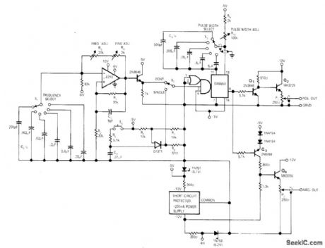
Frequency and pulse width are selected independently in decade steps with rotary switches. Vemier controls provide fine tuning and allow f up to 20% overlap of ranges. Rise and fall times are 100 ns or better. Both positive and negative outputs are provided, each adjustable from 0 to 10 V. S2 gives choice of continuous or single-pulse operation, and pushbutton S4 provides single-pulse outputs. μA710 comparator connected as astable MVBR provides trigger inputs for DM8850 retriggerable mono. Article gives circuit details and design equations.-C. Brogado, Versatile Inexpensive Pulse Generator, EDN|EEE Magazine, Oct. 1,1971, p 37-38. (View)
View full Circuit Diagram | Comments | Reading(752)
ACTIVE_ADJUSTABLE_BANDPASS_AUDIO_FILTER
Published:2009/7/14 3:49:00 Author:May


Has Butterworth attenuation characteristics and 42 db/octave cutoff slopes. Output is 50 v rms with low distortion, and dynamic range over 100 db. Second-order harmonic distortion is reduced by operating tube heaters at low voltage. Seven elements are varied simultaneously by switching different resistor and capacitor values to change cutoff frequencies. Article has three tables giving these values for high-pass cutoffs from 16 to 16,200 cps and low- pass cutoffs from 20 to 20,000 cps.-J. R. MacDonald, Active Bandpass Filter has Sharp Cutoff, Electronics, 31:33, p 84-87. (View)
View full Circuit Diagram | Comments | Reading(1745)
TWO_QUADRANT_SQUARING
Published:2009/7/14 3:49:00 Author:May
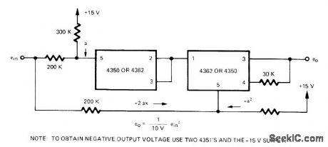
Teledyne Philbrick log modules are used in simple two-quadrant squarer in which input is offset becausemodules accept only one polarity Circuit shown provides positive output voltage.-''Aρplications for Models 4350/4351 & 4362/4363 Logarithmic Amplifiers,″ Teledyne Phillbrick,Dedham,MA ,974, AN-14. (View)
View full Circuit Diagram | Comments | Reading(455)
SINGLE_FET_CASCODE
Published:2009/7/14 3:49:00 Author:May


Costs less than two-fet version, but has somewhat poorer stability. Voltage gain is 500 for 33,000-ohm output impedance.-B,Smith, Low-Noise FETs sound Good to Circuit signers,Electronics,37:31,p 58-62. (View)
View full Circuit Diagram | Comments | Reading(570)
BIT_RATE_GENERATOR
Published:2009/7/15 4:30:00 Author:Jessie
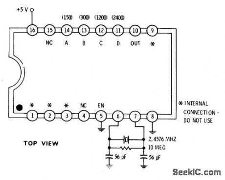
Fairchild 4702 IC synthesizes frequencies most often used in serial data communication, particularly with UARTS. With connections shown, output is 1760 Hz which is 16 x 110-baud rate of serial teletypes. Grounding only pin A generates 16 x 150 bauds. Grounding only pin B gives 16 x 300 bauds, grounding pin C gives 16 x 1200 bauds, and grounding pin D gives 16 x 2400 bauds. Will drive one regular TTL load at supply drain of 1 mA.-D. Lancaster, CMOS Cookbook, Howard W. Sams, Indianapolis, IN, 1977, p 155. (View)
View full Circuit Diagram | Comments | Reading(868)
05_mA_FOR_0_50_KILOHMS
Published:2009/7/14 3:48:00 Author:May
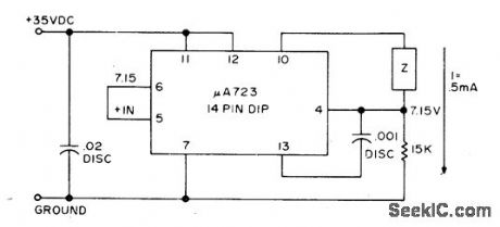
Current source uses Fairchild μA723 voltage regulator operating from ordinary unregulated supply not over 40 VDC. Regulator has built-in 7.15-V reference. Output current is well within 1% of 0.5 mA for load impedances from 0-50k. -L. Nickel, Constant Current Sources, 73 Magazine, March 1974, p29
(View)
View full Circuit Diagram | Comments | Reading(431)
1_MHz_SQUARE_WAVE_FOR_TDR
Published:2009/7/15 4:22:00 Author:Jessie
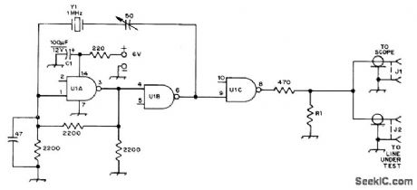
Fast-rise-time 1-MHz pulse generator serves with wide-band CRO and T connector for time-domain reflectometry (TDR) setup used to pinpoint exact location of fault in transmission line. Will also locate multiple faults along line, measure SWR, and measure characteristic impedance of cable. With 1-MHz square-wave source having 500-ns duration for positive portions of wave, cables up to 150 feet long can be tested. R1 should equal characteristic impedance of line being tested. U1 is Signetics N7400A or equivalent quad NAND/NOR gate. Article gives instructions for use.-W. Jochem, An Inexpensive Time-Domain Reflectometer, QST, March 1973, p 19-21. (View)
View full Circuit Diagram | Comments | Reading(2871)
ASYMMETRICAL_PULSE_GENERATOR
Published:2009/7/15 4:20:00 Author:Jessie
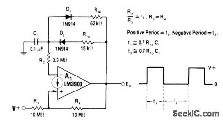
Charge and discharge paths of timing capacitor C1 in LM3900 IC connected as astable oscillator are individually controlled by D1 and D2. Value of R1a controls charge rate of C1 and period t1, while R1b controls discharge rate and period t2. Resistors can be pots for providing variable pulse width and repetition rate. For constant frequency with variable duty cycle, R1 can be single pot with ends going to D1 and D2 and tap going to output. For values shown, t1 is 1 ms and t2 is 4 ms.-W. G. Jung, IC Op-Amp Cook-book, Howard W. Sams, Indianapolis, IN, 1974, p 505.
(View)
View full Circuit Diagram | Comments | Reading(896)
| Pages:151/471 At 20141142143144145146147148149150151152153154155156157158159160Under 20 |
Circuit Categories
power supply circuit
Amplifier Circuit
Basic Circuit
LED and Light Circuit
Sensor Circuit
Signal Processing
Electrical Equipment Circuit
Control Circuit
Remote Control Circuit
A/D-D/A Converter Circuit
Audio Circuit
Measuring and Test Circuit
Communication Circuit
Computer-Related Circuit
555 Circuit
Automotive Circuit
Repairing Circuit