
Amplifier Circuit
Index 75
GROUNDED_GRID_STRIP
Published:2009/7/16 2:31:00 Author:Jessie
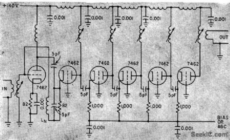
Six-stage low-noise 60-Mc i-f strip amplifier, using microminiature ceramic triodes, gives 75-db overall gain, 1.7-db noise figure, and 6.5.Mc bandwidth.First stage is cascode and other five are grounded-grid triodes.-J. W. Rush, Designing Grounded-Grid Amplifiers with Controlled Gain, Electronics, 33:52, p 50-53. (View)
View full Circuit Diagram | Comments | Reading(754)
500_MC_STAGGER_TUNED_I_F
Published:2009/7/16 2:30:00 Author:Jessie
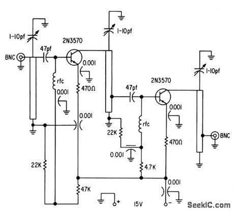
Slight staggering in two stages gives excellent stability, so circuit will not oscillate when either source or load is open. Bandwidth is 90 Mc for 1 db down and 110 Mc for 3 db down, with midband gain of 21 db. Draws only 7 mc at 15 V.-Texas Instruments Inc., Solid-State Communications, McGraw-Hill, N.Y., 1966, p 315. (View)
View full Circuit Diagram | Comments | Reading(646)
TWO_CHIP_LOW_COST_STRIP
Published:2009/7/16 2:30:00 Author:Jessie
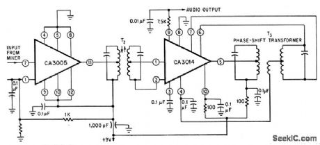
Detector and 10.7-Mc i-f strip give 95 db gain. Differential amplifier in both RCA chips provides symmetrical limiting over wide input voltage range. Audio output is 220 my.-R. L. Sanquini, Integrated Circuits Make A Low-Cost F-M Receiver, Electronics, 39:16, p l33-138. (View)
View full Circuit Diagram | Comments | Reading(872)
I_F_TUNING_WITH_DELAY_LINE
Published:2009/7/16 2:29:00 Author:Jessie
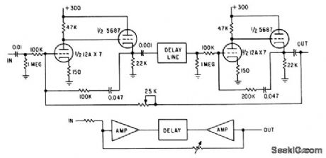
Circuit gives Q of 285 at 500 kc, and is tuned by adjusting delay time. Can be used in any system where high gain, high Q, and stability are needed.-I. F. Barditch, Delay-Line Controls Tuned Amplifier, Electronics, 33:31, p 108. (View)
View full Circuit Diagram | Comments | Reading(651)
60_MC_TETRODE_I_F
Published:2009/7/16 2:28:00 Author:Jessie
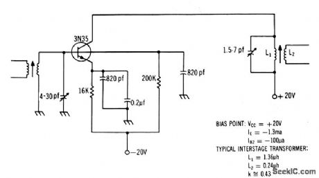
Use of 3N35 gives excellent agc characteristics, Stage gain is 12 db.-Texas Instruments Inc., Solid-State Communications, McGraw-Hill, N,Y., 1966, p 3. (View)
View full Circuit Diagram | Comments | Reading(718)
PULSED_GATED_30_MC_I_F_
Published:2009/7/16 2:27:00 Author:Jessie
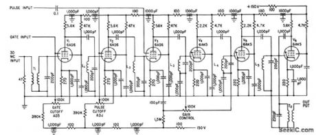
Control signals are fed to suppressor grids of early amplifier stages, to generate groups of i-f pulses for simulating radar scanning or for testing transient response of i-f circuits. Bandwidth is 1.2 Mc.-C. D. Rasmussen, Suppressor Gating for I-F Amplifiers, Electronics, 34:34, p 62. (View)
View full Circuit Diagram | Comments | Reading(617)
70_MC_NEUTRALIZED
Published:2009/7/16 2:26:00 Author:Jessie
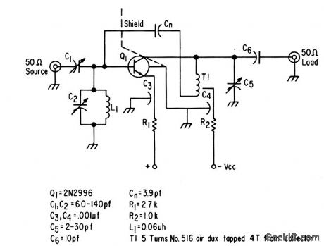
Designed to give maximum power gain in single stage while maintaining good stability. Noise figure is less than 3 db with power gain of 27 db.-Texas Instruments Inc., Solid-Stale Communications, McGraw-Hill, N.Y., 1966, p 313. (View)
View full Circuit Diagram | Comments | Reading(621)
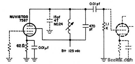
BILATERAL_AMPLIFIER
Published:2009/7/13 21:19:00 Author:May
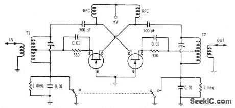
When switch is in position shown, signal entering through T1 is amplified by first transistor and fed from its drain terminal to output through resonant transformer T2. Second transistor is not operational because it now has cutoff bias between gate and source. When switch position is reversed, incoming signal is applied to transistor at right through T2 and removed from left side of circuit to give changeover in signal direction. First transistor is inactive now.-E. M. Noll, FET Principles, Experiments, and Projects, Howard W. Sams, Indianapolis, IN, 2nd Ed., 1975, p 198-199. (View)
View full Circuit Diagram | Comments | Reading(702)
TUNE_UP_AID
Published:2009/7/13 21:18:00 Author:May
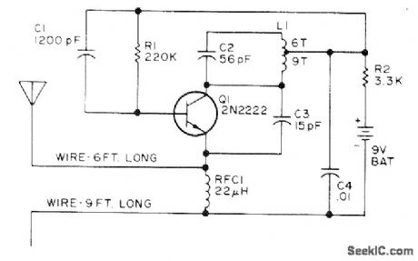
Superregenerative receiver circuit is modified to bring quenching frequency down into audio range, thereby giving many closely spaced carriers in region of 27 MHz. RF level across frequency range is essentially constant. Signal simplifies tune-up of front ends of CB units. Antenna is 6 feet of wire connected to emitter side of RFC, with 9 feet of wire on battery side of RFC as counterpoise. Combination, with circuit in center, can be hung vertically in tree if means can be provided for turning it off or removing battery when not in use. Drain is about 0.5 mA from 9-V battery.-E. A. Lawrence, Citizens Band Alignment Aid, 73 Magazine, April 1973, p 87-88. (View)
View full Circuit Diagram | Comments | Reading(3229)
AMPLIFIER_DRIVER_SPEEDS_UP_COUNTER
Published:2009/7/13 20:41:00 Author:May
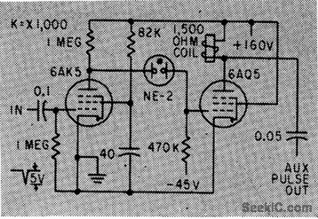
Arrangement using neon coupling between tubes can increase operating speed of well.designed electromechanical counter up to 2.5 times, by providing combination of pulsed and sliding overvolting.-R.L. lves, Circuit Modifications for Boosting Counter Speed, Electronics, 33:7, p112-114. (View)
View full Circuit Diagram | Comments | Reading(648)
TACHOMETER_AMPLIFIER
Published:2009/7/16 3:32:00 Author:Jessie
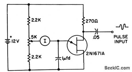
Unijunction transistor is basis of simple, inexpensive tachometer amplifier or frequency meter. Each negative input pulse of sufficient amplitude triggers ujt, so capacitor is discharged through ujt. Capacitor is then recharged through d-c am meter by current having sawtooth waveform that minimizes flutter at low frequencies.-T. P. Sylvan, Frequency Meter-Tachometer Amplifier, EEE, 10:8, p 25-26. (View)
View full Circuit Diagram | Comments | Reading(913)
LOGARITHMIC_THIN_FILM_I_F_AMPLIFIER
Published:2009/7/16 3:00:00 Author:Jessie

Un-tuned stages eliminate need for inductors in 60-Mc log i-f module while giving gain of 10 db,-R.Leslie and Townsend, Inductors No Problem: New Thin-Film Amplifier, Electionics,36:23, p 46-49. (View)
View full Circuit Diagram | Comments | Reading(552)
LOW_Q_22_MC_I_F_DESIGN
Published:2009/7/16 2:59:00 Author:Jessie
Article gives detailed design procedure, with example worked out for 480-kc bandwidth and gain of 92 db. For high-Q stage, 1.1 K load resistor is changed to 12K.-J. F. Klarl, A Systematic Approach For Designing IF Amplifiers, EEE, 12:3, p 40-44. (View)
View full Circuit Diagram | Comments | Reading(648)
SINGLE_TRANSISTOR_I_F_AMPUFIER
Published:2009/7/16 2:59:00 Author:Jessie
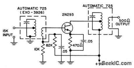
Designed for broadcast-band transistor radio. Neutralization is unnecessary with 2N293 rate-grown npn transistor used.-Transistor Manual, Seventh Edition, General Electric co.,1964, p 285. (View)
View full Circuit Diagram | Comments | Reading(720)
60_MC_I_F_WITH_2N743
Published:2009/7/16 2:58:00 Author:Jessie
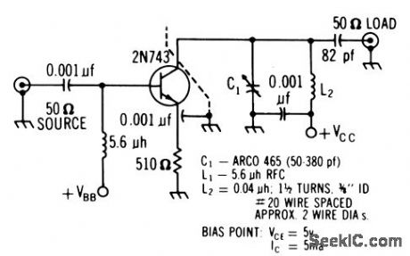
Silicon epitaxial transistor has unconditional stability at this frequency, simplifying alignment. Gains up to 16 db per stage are possible with conjugate match at output. Noise figure is good.-Texas Instruments Inc., Solid-State Communications, McGraw-Hill, N.Y., 1966, p 311. (View)
View full Circuit Diagram | Comments | Reading(916)
MOBILE_I_F
Published:2009/7/16 2:58:00 Author:Jessie
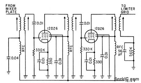
Two 455-kc i-f stages provide gain of 20 per stage and average band-width of 12 kc.-C. Gonzalez and R. J. Nelson, Design of Mobile Receivers with Low-Plate-Potential Tubes, Electronics, 33:34, p62-65. (View)
View full Circuit Diagram | Comments | Reading(600)
55_MC_THREE_STAGE_GERMANIUM
Published:2009/7/16 2:56:00 Author:Jessie
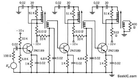
Mid-band gain is 60 db and 3-db bandwidth is 200 kc.Interstage networks consist of single-tuned transformers with collectors topped down on primary.-Texas Instruments Inc., Transistor Circuit Design, McGraw-Hill, N.Y., 1963, p 294. (View)
View full Circuit Diagram | Comments | Reading(751)
60_MC_SILICON_TETRODE_STAGE
Published:2009/7/16 2:55:00 Author:Jessie

Used in eight-stage strip having identical stages except for input and output, whose transformers are designed for driving and load resistances. Transitionally coupled doubletuned interstages are used, with 5:1 mismatch providing stability and ease of alignment dong with stage gain of 12.5 db.-Texas Instruments Inc., transistor Circuit Design, McGraw-Hill, N.Y., 1963, p 292. (View)
View full Circuit Diagram | Comments | Reading(615)
CERAMIC_FILTER_I_F_STAGE
Published:2009/7/16 2:53:00 Author:Jessie

Article covers design procedure using transistor signal handling curves. Collector resistance is used to minimize drift.-W. Rheinfelder, Using Transistor Signal Handling Curves in Receiver Design, EEE, 14:6, p 62-66. (View)
View full Circuit Diagram | Comments | Reading(666)
55_MC_I_F
Published:2009/7/16 2:52:00 Author:Jessie
Three germanium transistors give power gain of 62 db with noise figure of only 4 db for bandwidth of 0.18 Mc.-Texas Instruments Inc., Solid-State Communications, McGraw-Hill, N. Y., 1966. p 307. (View)
View full Circuit Diagram | Comments | Reading(605)
| Pages:75/250 At 206162636465666768697071727374757677787980Under 20 |
Circuit Categories
power supply circuit
Amplifier Circuit
Basic Circuit
LED and Light Circuit
Sensor Circuit
Signal Processing
Electrical Equipment Circuit
Control Circuit
Remote Control Circuit
A/D-D/A Converter Circuit
Audio Circuit
Measuring and Test Circuit
Communication Circuit
Computer-Related Circuit
555 Circuit
Automotive Circuit
Repairing Circuit