Amplifier Circuit
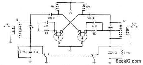
BILATERAL_AMPLIFIER
Published:2009/7/13 21:19:00 Author:May | From:SeekIC

When switch is in position shown, signal entering through T1 is amplified by first transistor and fed from its drain terminal to output through resonant transformer T2. Second transistor is not operational because it now has cutoff bias between gate and source. When switch position is reversed, incoming signal is applied to transistor at right through T2 and removed from left side of circuit to give changeover in signal direction. First transistor is inactive now.-E. M. Noll, FET Principles, Experiments, and Projects, Howard W. Sams, Indianapolis, IN, 2nd Ed., 1975, p 198-199.
Reprinted Url Of This Article:
http://www.seekic.com/circuit_diagram/Amplifier_Circuit/BILATERAL_AMPLIFIER.html
Print this Page | Comments | Reading(3)

Article Categories
power supply circuit
Amplifier Circuit
Basic Circuit
LED and Light Circuit
Sensor Circuit
Signal Processing
Electrical Equipment Circuit
Control Circuit
Remote Control Circuit
A/D-D/A Converter Circuit
Audio Circuit
Measuring and Test Circuit
Communication Circuit
Computer-Related Circuit
555 Circuit
Automotive Circuit
Repairing Circuit
Code: