
Circuit Diagram
Index 202
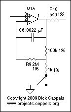
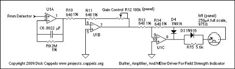
Simple Field Strength Indicator
Published:2013/1/16 2:14:00 Author:muriel | Keyword: Simple, Field Strength, Indicator

View full Circuit Diagram | Comments | Reading(741)
The Power Supply
Published:2013/1/16 2:13:00 Author:muriel | Keyword: Power Supply

View full Circuit Diagram | Comments | Reading(652)
the first amplfier
Published:2013/1/16 2:12:00 Author:muriel | Keyword: amplfier
View full Circuit Diagram | Comments | Reading(605)
The amplifier board
Published:2013/1/16 2:12:00 Author:muriel | Keyword: amplifier board
View full Circuit Diagram | Comments | Reading(771)
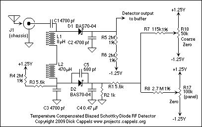
RF detector
Published:2013/1/16 2:11:00 Author:muriel | Keyword: RF detector
View full Circuit Diagram | Comments | Reading(1313)
Field Strength Meter Using A Biased Schottky Detector
Published:2013/1/16 2:11:00 Author:muriel | Keyword: Field Strength Meter, Biased Schottky Detector

View full Circuit Diagram | Comments | Reading(1169)
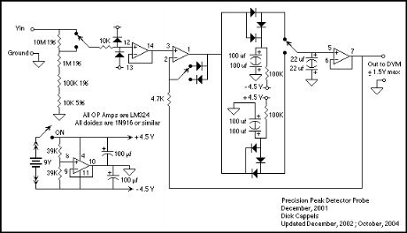
Precision Audio Frequency Peak Detecting Probe
Published:2013/1/16 2:10:00 Author:muriel | Keyword: Precision Audio Frequency, Peak Detecting Probe
View full Circuit Diagram | Comments | Reading(941)
frequency divider
Published:2013/1/16 2:09:00 Author:muriel | Keyword: frequency divider

View full Circuit Diagram | Comments | Reading(0)
Power supply and Reference Signal
Published:2013/1/16 2:09:00 Author:muriel | Keyword: Power supply , Reference, Signal

View full Circuit Diagram | Comments | Reading(720)
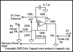
Output Amplifier
Published:2013/1/16 2:08:00 Author:muriel | Keyword: Output Amplifier
View full Circuit Diagram | Comments | Reading(623)
P-P Detector and Voltage Follower
Published:2013/1/16 2:08:00 Author:muriel | Keyword: P-P Detector, Voltage Follower

View full Circuit Diagram | Comments | Reading(1144)
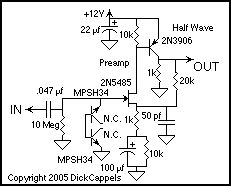
Input coupling and Preamp
Published:2013/1/16 2:07:00 Author:muriel | Keyword: Input coupling , Preamp
View full Circuit Diagram | Comments | Reading(581)
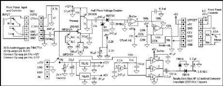
HF AC Millivoltmeter Adapter
Published:2013/1/16 2:07:00 Author:muriel | Keyword: HF , AC, Millivoltmeter, Adapter
View full Circuit Diagram | Comments | Reading(2640)
PWM with 555
Published:2013/1/16 1:49:00 Author:muriel | Keyword: PWM , 555

View full Circuit Diagram | Comments | Reading(2386)
Dual Led Flasher
Published:2013/1/16 1:48:00 Author:muriel | Keyword: Dual Led Flasher

View full Circuit Diagram | Comments | Reading(799)
Timer with 555
Published:2013/1/16 1:47:00 Author:muriel | Keyword: Timer, 555

This circuit can be used to activate a relay for two or three minutes. Pressing the switch the relay will be activated. Changing the 1M resistor with a variable resistor you can vary the time. The 0.01 capacitor is important because it prevents any false triggering.
The circuit will work OK with 6 Volts without any modification. If you want to use 9 or 12 Volts, you need to change the relay with a 9V or 12V relay. Using this circuit with 120 VAC is not recommended, however, using the right parts and the right isolation, will be not a problem.
The aplications for this circuit may vary, for example: Bouce-free switch, A three-minutes light to walk thru a dark area, A timer-activated faucet to save water, etc. Any project that needs only a few minutes of power will be perfect for this circuit. Ever if you have an old microwave with the broken electronic control, you can replace it with this timer (using the right hi-current relay). (View)
View full Circuit Diagram | Comments | Reading(1997)
LM6172 voltage feedback amplifier and its pin main characteristics
Published:2013/1/16 1:14:00 Author:Ecco | Keyword: voltage feedback amplifier , pin main characteristics
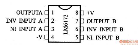
Operating voltage range is ± 5.0 to ± 15V; unity gain bandwidth is 110MHz; conversion rate is 3000V/μs; supply current is 4.6mA; Output Current is 50mA / channel; Input Offset Voltage is 0.4mA; input bias current is 1.2μA; common-mode input resistance is 40MΩ; differential input resistance is 4.9MΩ; PSRR = 95dB ; CMRR = 110dB.
(View)
View full Circuit Diagram | Comments | Reading(778)
LM6181 current feedback amplifier and its pin main characteristics
Published:2013/1/16 1:32:00 Author:Ecco | Keyword: current feedback amplifier , pin main characteristics
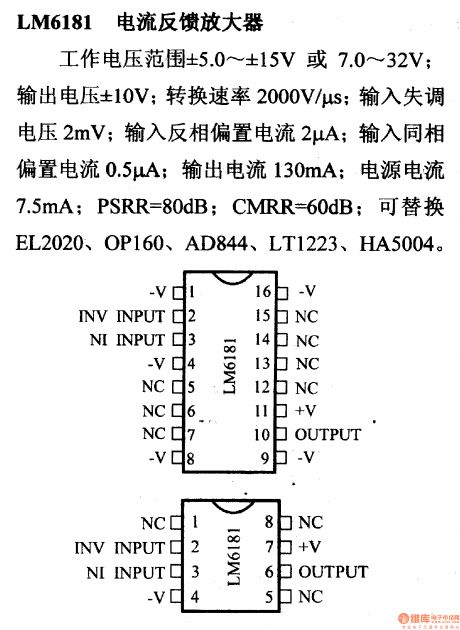
Operating voltage range is ± 5.0 ~ ± 15V or 7 ~~ 32V; output voltage is ± 10V; conversion rate is 2000mV/μs; input offset voltage is 2mV; reversed input bias current is 2μA; input in-phase bias current is 0.5μA; Output Current is 130mA; power current is 7.5mA; PSRR = 80dB; CMRR = 60dB; it can replace EL2020, OP160, AD844, LT1223 and HA5004.
(View)
View full Circuit Diagram | Comments | Reading(836)
MA337 JFET input op amp and its pin main characteristics
Published:2013/1/16 1:35:00 Author:Ecco | Keyword: JFET input, op amp , pin main characteristics
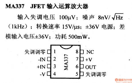
The input offset voltage is 100μV; noise is 8nV / √ ¯ Hz ( 1kHz); conversion rate is 15V/μs; power supply is ± 36V; differential-mode input voltage is ± 36V, the power consumption is 500mW.
(View)
View full Circuit Diagram | Comments | Reading(624)
MC13060 power amplifier and its pin main characteristics
Published:2013/1/16 1:01:00 Author:Ecco | Keyword: power amplifier , pin main characteristics
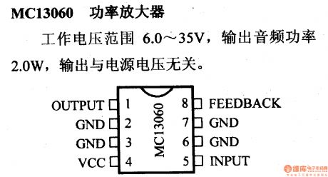
The operating voltage range is 6.0 ~ 35V, and the output audio power is 2.0W, and there is no relationship between output and power supply voltage.
(View)
View full Circuit Diagram | Comments | Reading(630)
| Pages:202/2234 At 20201202203204205206207208209210211212213214215216217218219220Under 20 |
Circuit Categories
power supply circuit
Amplifier Circuit
Basic Circuit
LED and Light Circuit
Sensor Circuit
Signal Processing
Electrical Equipment Circuit
Control Circuit
Remote Control Circuit
A/D-D/A Converter Circuit
Audio Circuit
Measuring and Test Circuit
Communication Circuit
Computer-Related Circuit
555 Circuit
Automotive Circuit
Repairing Circuit