
Circuit Diagram
Index 1516
The synchronous wave detection circuit of full method
Published:2011/7/17 21:02:00 Author:Borg | Keyword: synchronous, wave detection circuit
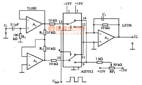
In the figure is the synchronous wave detection circuit of full method. In the circuit, A1 and A2 can compose the balance output circuit of forward/backward phase output, even when the R2/R3 ratio is 1. the analog switch AD7512 plays an important role, the figured connector position is the inverting input terminal of the forward output(A1 output is the forward hemi-cycle of the input signal) linking to A3; if the connector is lower, the inverting output (A2 output is the backward hemi-cycle) is conducting. Considering the period of an input signal in the way, A3 output terminal can get a full-wave output.
(View)
View full Circuit Diagram | Comments | Reading(928)
The Value of Q and Frequency Adjustable Narrow-band Filter Circuit
Published:2011/7/14 20:17:00 Author:Joyce | Keyword: Q , Frequency, Adjustable, Narrow-band, Filter
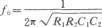
As shown in the figure is the value of Q and frequency adjustable narrowband filter circuit. This circuit shows an active narrowband filter whose value of Q and frequency are adjustable. Its positive feedback takes the form of Wien-bridge, while its loop gain is less than one. The characteristic of this circuit is that the center frequency will not be influenced by the regulation of the value of Q, because it is only relevant with the loop gain. When the gain is 600,the value of Q is 2000; when the gain is 140, the value of Q is 30. In general, in Wien-bridge oscillators, the amplifier's gain must be greater than 3 to produce oscillation for non-inverting input ends, but the gain of the amplifier in this circuit is less than 3. The resonance frequency of the circuit is:
(View)
View full Circuit Diagram | Comments | Reading(566)
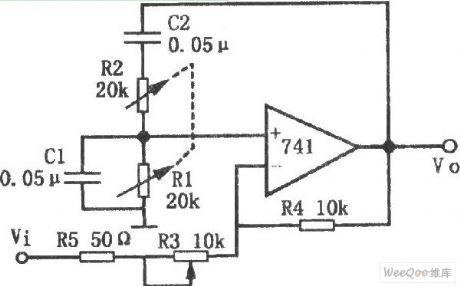
C51 Single-Chip Microcomputer Serial Communication Hardware Circuit
Published:2011/7/15 1:58:00 Author:Joyce | Keyword: C51 Singlechip, Serial Communication , Hardware
The full-duplex serial communication mouth of 51 SCM makes it convenient to have serial communication between a single chip microcomputer and a computer .But there’s some requirements for serial communication , such as serial port of the computer should be RS232 level ,while that of the SCM is TTL level; a level conversion circuit is needed between them. Here we use a dedicated chip MAX232 for conversion. A few triodes can be used to conduct simulated conversion as well, but it is more simple and reliable to use dedicated chips. We connect the serial ports in three-wire system.
(View)
View full Circuit Diagram | Comments | Reading(918)
Multifunctional Active Filter Circuit
Published:2011/7/14 20:21:00 Author:Joyce | Keyword: Multifunctional , Active , Filter
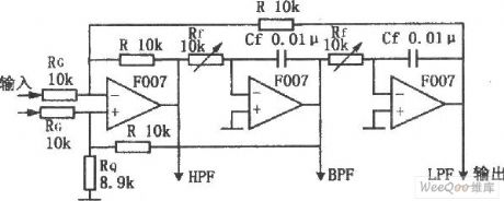
This circuit is composed of three operational amplifiers and resistance components, and its main characteristic is that it can get filtering properties of high-pass, low-pass and band-pass. In addition, once the values of Rf、Cf are changed, the bandpass characteristics can be ensured in a wide range without any interference between the circuit gain and the value of Q . This circuit is simple and easy to adjust . Also it is stable.
(View)
View full Circuit Diagram | Comments | Reading(531)
K6274K and K6274D-the image intermediate frequency band pass filter integrated circuit
Published:2011/7/15 19:52:00 Author:Borg | Keyword: intermediate frequency, band pass

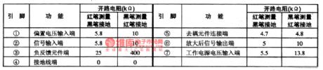
K6274K and K6274D belong to a kind of image intermediate frequency band pass filter integrated circuit, which are widely used in Konka S serial large screen color TV sets.1. Function featuresK6274K and K6274D contain the eclipse PAL/NTSC switch control circuit, band pass filter circuit and other additional function circuits.2. pin functions and dataK6274K and K6274D are in the 5-pin single in-line package, which are in Konka P2960S and P2971S large screen color TV sets, and the pin functions and data are listed in table 1-1.
table 1-1 pin functions and data of K6274K and K6274D (View)
View full Circuit Diagram | Comments | Reading(847)
IN706, 1N711 and 1N712—the karaoke mixed digital integrated circuit
Published:2011/7/15 20:07:00 Author:Borg | Keyword: karaoke, integrated circuit


1.the internal circuit of 1N706The internal circuit of N706 is shown in figure 1-1, which contains the mixed and coupled low-pass, high-pass, A/D, D/A and clock oscillating circuit, etc. besides, there is a function of sleep for selection which can reduce the power consumption, so it’s convenient to save the power consumption of users.
2. the main parameters of 1N706, 1N711 and IN7121N706, 1N711 and IN712 have the following main parameters. The power supply voltage is +5V, the static working current is 18MA; when RL=47K, the voltage gain is 2.5dB; when THD=10%, the max output voltage is 1V.
(View)
View full Circuit Diagram | Comments | Reading(1089)
The power supply and starting circuit of Nanjing-Iveco light car
Published:2011/7/15 20:21:00 Author:Borg | Keyword: power supply, light car, Nanjing-Iveco
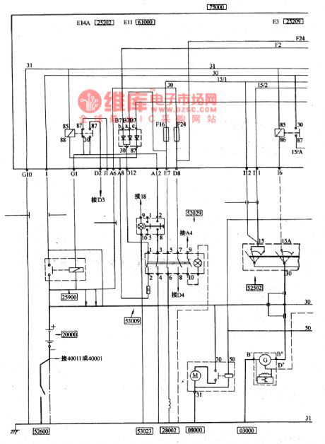
(4) power supply, starting and pre-heatingThe negative pole of the battery 20000 is bonded by the manual switch 52600, the mode of the battery is 12V88Ah (or 12V110Ah), its positive pole is connected with the central connection box 75000 by the electromagnet power supply general switch 25900, and another main stream is connected with the starter 08000, the fire wire of the AC motor 03000 is linked to the positive pole of the battery from the motor B+ cylinder. Therefore, as long as the manual switch 52600 is connected, the generator can charge the battery directly when it is running, whether the charge is normal can be indicated by the charge indicator 58100 on the dashboard.
(View)
View full Circuit Diagram | Comments | Reading(406)
CAT24C16—the E(2)PROM storage integrated circuit
Published:2011/7/15 20:31:00 Author:Borg | Keyword: storage, integrated circuit
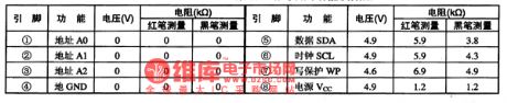
CAT24C16 is an E(2)PROM programmable storage, which is used in the assembling circuit of Changhong 5lPT28T rear projector color TV sets to store the standard data of concentrating regulation.1.function featuresCAT24C16 contains the erasable and programmable read-only storage of 1024X16bit, IC general circuit, address signal process circuit, writing protection circuit and other additional function circuits.2.pin functions and dataCAT24C16 is in 8-pin dual in-line package, whose pin functions and data are listed in table 1.
(View)
View full Circuit Diagram | Comments | Reading(346)
ICE1QS01—the integrated circuit of the new switch power supply quasi-resonance controller
Published:2011/7/15 20:58:00 Author:Borg | Keyword: integrated circuit, switch power supply, quasi-resonance controller


ICE1QS01 is an integrated circuit of the new switch power supply quasi-resonance controller, which is used in the TV, VCR and DVD player, satellite receiver, laptop charger and other switch power supply.1. the internal circuitICE1QS01 integrates the digit processor, standby abrupt mode and reversing point adjusting circuit, whose internal circuit is shown in Figure 1-1.
Figure 1-1 the internal circuit of ICE1QS012. pin functions and dataICE1QS01ES is in 8-pin DIP package, whose pin functions and data are listed in table 1-2.
(View)
View full Circuit Diagram | Comments | Reading(3755)
IAP722-the FM high frequency resonance integrated circuit
Published:2011/7/15 21:07:00 Author:Borg | Keyword: high frequency, resonance integrated circuit


IAP722 is a FM high frequency resonance integrated circuit, which is used in low voltage radios and walkmen.1. the internal circuit and pin functions of IAP722IAP722 contains the FM AGC, local oscillation, mix, buffering amplifier and other circuits. The IC is in 9-pin single line package, whose internal circuit is shown in figure 1-1, and pin functions and data is listed in table 1-1.
Figure 1-1 the internal circuit of IAP722Table 1-1 pin functions and data of IAP722
2. the typical application circuit of IAP722
(View)
View full Circuit Diagram | Comments | Reading(898)
The thermometer composed of diode temperature sensors
Published:2011/7/17 20:01:00 Author:Borg | Keyword: thermometer, temperature sensors

This is the thermometer composed of diode temperature sensors. In the circuit, R1 and RP1 make VD have a constant current of 0.5mA, R2 and R3 are both the forward feedback resistors, which make the linearity under 2%. In the temperature range of -20-+5O℃, the output sensitivity of A1 is -2OmV/℃. By adjusting RP2, when it is O℃, A2 outputs a voltage of 0V. If the gain of A2 is set to be 5 times, the sensitivity will be 0.1v/℃, which can be connected with the digital multi-meter, so the temperature under test can be read out directly.
(View)
View full Circuit Diagram | Comments | Reading(1536)
The tune circuit composed of MOSFET and inductance coils
Published:2011/7/17 20:24:00 Author:Borg | Keyword: tune circuit, inductance coils
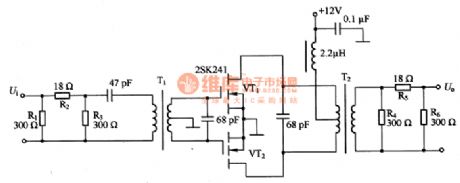
This is the tune circuit composed of MOSFET and inductance coils, which can only amplify the signals of certain frequency, it is fitted in the terminal circuit of low power emitters. The circuit is in push-pull pattern, so there few odd harmonic waves, its gain without connecting with attenuator is +20~+30dB at the frequency of 14MHZ. in the circuit, R1, R2 and R3 composed the input attenuator, R4, R5 and R6 form the output attenuator; VT1 and VT2 are the 2SK241 power MOSFET. If larger gain and output power are needed, one more parallel 2SK241 can meet the need. When the gain is two large and the impedance may be mismatching, an attenuator can be fixed in it.
(View)
View full Circuit Diagram | Comments | Reading(658)
AN360—the low noise audio preamplifier integrated circuit
Published:2011/7/15 19:38:00 Author:Borg | Keyword: audio preamplifier, integrated circuit

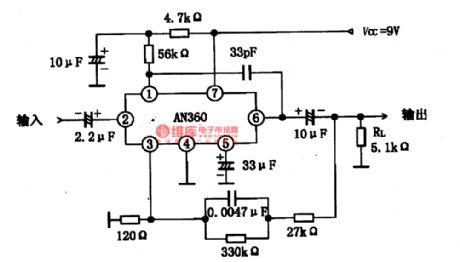
AN360 is a low-noise audio preamplifier integrated circuit produced by Panasonic, which is used in domestic stereo systems as the audio preamplifier.1. the internal circuit and pin functions of AN360AN360 consists of 3 stages of amplifiers, and voltage gain of its open loop equivalent circuit is high, the 1st loading resistor can be connected externally, a proper amplifier can be chosen. The IC is in 7-pin single in-line package, whose internal equivalent circuit is shown in figure 1-10, and pin functions and data are listed in table 1.
(View)
View full Circuit Diagram | Comments | Reading(3433)
The warm air sensor circuit composed of LM334
Published:2011/7/17 22:24:00 Author:Borg | Keyword: warm air, sensor

In the figure is the warm air sensor circuit composed of LM334. LM334(2) is used to test the warm air temperature (Ts); LM334(1) is used to the outside temperature (TA). LM334 sensor is to converter the 1K thermodynamics temperature into the 214μV voltage, so if the voltage difference of (Us-UA) is tested, the temperature difference of (Ts-TA) can be got. The voltage U1 and UA can be got by the circuit composed of RP1, R3 and VT1, and US=UA+Ul, therefore, TS=TA+TI (i.e Ul/2l4μV). (Ts-TA) is set by RP1.
(View)
View full Circuit Diagram | Comments | Reading(1473)
The FM intermediate frequency amplifier integrated circuit
Published:2011/7/15 20:45:00 Author:Borg | Keyword: intermediate frequency amplifier, integrated circuit
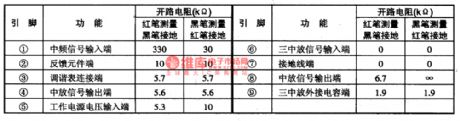
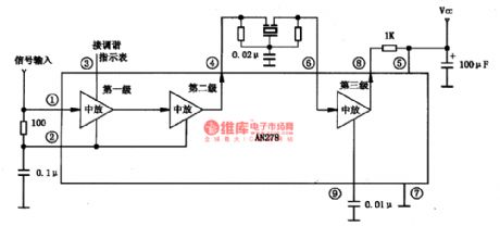
AN278 is a FM intermediate frequency amplifier integrated circuit produced by Panasonic, which is used in domestic stereos and FM radios as the FM intermediate frequency amplifier.1. the internal circuit and pin functions of AN278The features of AN278 are that the LEV fault of the internal amplitude limiter is low, the symmetry is good; the 2nd and 3rd is coupled directly, and they can also connected with pottery filter: when the PLL circuit is working, the limiter can offer enough LEV; it can be connected with the tune indicating circuit, etc. AN278 is in single 9-pin in-line package.
(View)
View full Circuit Diagram | Comments | Reading(1171)
The phase wave detection composed of 74HC4053
Published:2011/7/17 20:36:00 Author:Borg | Keyword: phase wave, detection circuit
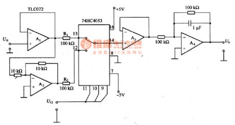
This is the phase wave detection circuit composed of 74HC4053. the circuit consists of the computing amplifier TLC072 and the analog switch 74HC4053, but the conducting resistance of the analog switch changes with the temperature and the power supply voltage. In the circuit, the output of the analog switch 74HC4053 is connected with the voltage follower composed of A3, so the conducting resistance doesn’t affect the output. If the impedance of the input signal is very low, then A1 is needless. Although the 74HC analog switch can’t be assure of “breading first, connecting second”, if 74HC4053 makes both A1 and A2 short, it won’t problematic.
(View)
View full Circuit Diagram | Comments | Reading(3012)
Adjustable Power Supply Circuit of IR2111
Published:2011/7/17 5:34:00 Author:Michel | Keyword: Adjustable Power Supply Circuit

The adjustable power supply circuit of IR2111 is shown as above.In the circuit,IR2111 adopts VD3 and C1 to generate the boost voltage which is more than 12V.Thus it is not necessary to use high grade driving power supply.AC11OV turns into 140V DC voltage after VDB rectifying and it drops to 24V after flowing through VT1 and VD1.And then it provides 12V voltage for IR2111 after flowing through three ports regulator 7812. PWM output of half bridge switch power supply turns into DC voltage Ui via smooth induction and capacitance and it is added to port 2 and 3 of TLP559. (View)
View full Circuit Diagram | Comments | Reading(9103)
P83C266BDR Single-chip Microcomputer Integrated Circuit
Published:2011/7/17 6:32:00 Author:Michel | Keyword: Microcomputer Integrated Circuit


P83C266BDR is latest eight high speed digital CMOS central microcomputer monolithic integrated circuit prdoduced by Philips.It is designed for Konka series mirror TVs, such as P3486C type machine etc.
First,Fucntions
P83C266BDR integrated circuit contains the central microprocessor (CPU), electric programmable read-only memory (an EPROM), random access memory (RAM), input and output interface (I/O), l6 bit timer/counter, A/D and D/A, OSD generator, the I2C bus SCL, SDA serial interface and pulse width modulation (PWM) circuit components etc.The inside circuit of the intergrated block is shown as picture 1.
Picture 1:The Inside Circuit of Intergrated Circuit (View)
View full Circuit Diagram | Comments | Reading(1027)
The air-conditioning system circuit of Shanghai GM Cadillac CTS(3)
Published:2011/7/18 19:20:00 Author:Borg | Keyword: air-conditioning system, Cadillac CTS
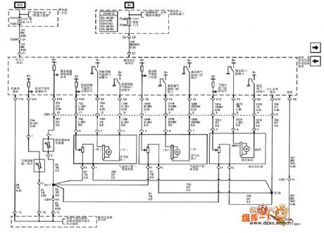
The air-conditioning system circuit of Shanghai GM Cadillac CTS(3)
(View)
View full Circuit Diagram | Comments | Reading(855)
The engine CMP, OKP and IOM circuit of Shanghai GM Buick-Century (2)
Published:2011/7/18 19:35:00 Author:Borg | Keyword: CMP, OKP, IOM, Buick-Century

Figure:The engine CMP, OKP and IOM circuit of Shanghai GM Buick-Century (2) (View)
View full Circuit Diagram | Comments | Reading(485)
| Pages:1516/2234 At 2015011502150315041505150615071508150915101511151215131514151515161517151815191520Under 20 |
Circuit Categories
power supply circuit
Amplifier Circuit
Basic Circuit
LED and Light Circuit
Sensor Circuit
Signal Processing
Electrical Equipment Circuit
Control Circuit
Remote Control Circuit
A/D-D/A Converter Circuit
Audio Circuit
Measuring and Test Circuit
Communication Circuit
Computer-Related Circuit
555 Circuit
Automotive Circuit
Repairing Circuit