Control Circuit
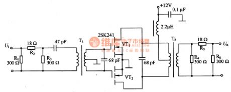
The tune circuit composed of MOSFET and inductance coils
Published:2011/7/17 20:24:00 Author:Borg | Keyword: tune circuit, inductance coils | From:SeekIC

This is the tune circuit composed of MOSFET and inductance coils, which can only amplify the signals of certain frequency, it is fitted in the terminal circuit of low power emitters. The circuit is in push-pull pattern, so there few odd harmonic waves, its gain without connecting with attenuator is +20~+30dB at the frequency of 14MHZ. in the circuit, R1, R2 and R3 composed the input attenuator, R4, R5 and R6 form the output attenuator; VT1 and VT2 are the 2SK241 power MOSFET. If larger gain and output power are needed, one more parallel 2SK241 can meet the need. When the gain is two large and the impedance may be mismatching, an attenuator can be fixed in it.
Reprinted Url Of This Article:
http://www.seekic.com/circuit_diagram/Control_Circuit/The_tune_circuit_composed_of_MOSFET_and_inductance_coils.html
Print this Page | Comments | Reading(3)

Article Categories
power supply circuit
Amplifier Circuit
Basic Circuit
LED and Light Circuit
Sensor Circuit
Signal Processing
Electrical Equipment Circuit
Control Circuit
Remote Control Circuit
A/D-D/A Converter Circuit
Audio Circuit
Measuring and Test Circuit
Communication Circuit
Computer-Related Circuit
555 Circuit
Automotive Circuit
Repairing Circuit
Code: