
Circuit Diagram
Index 1503
Application circuit diagram of W296 with reset functions
Published:2011/5/5 7:16:00 Author:Nicole | Keyword: reset function

Compared with other switching regulator, W296 has a feature: internal reset function, when the regulator's output voltage produces reset signal within correct limits. The reset is achieved by the reset input side 12-pin, delayed side 13-pin and reset output side 14-pin. When the 12-pin voltage is lower than 5V, reset output is turned into low level by the comparator of resetting circuit; when the 12-pin voltage is higher than 5V, the reset output side turns into high level whichis delayed ashort period of time, the overtime is determined by the delay capacitor which is connected to 13-pin. The value of reset capacitor is between 1 ~ 4.7μF, when it is 2.2μF, the delay time is l00ms. The reset output side is a open collector, an external resistor is required when it is used. There are two ways, one is the 12-pin connects to output side directly, the other is to connect a resistor on input side, then divide to 12-pin, as shown. (a)connect output; (b)connect input.
(View)
View full Circuit Diagram | Comments | Reading(531)
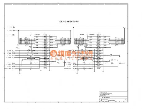
PC mainboard circuit 440BX-12
Published:2011/6/30 22:09:00 Author:zj | Keyword: PC mainboard, 440BX-12

View full Circuit Diagram | Comments | Reading(585)
Push-pull converter switching power supply circuit diagram
Published:2011/5/5 7:08:00 Author:Nicole | Keyword: switching power supply, push-pull converter

Push-pull converter switching power supply circuit. CW494 is a double-ended converter modulator integrated circuits, including error amplifier, voltage reference, clock oscillator, pulse width modulator and other circuits. Transformer T1 is a high-frequency transformer which can transferenergy to the load. T2 is incentive to promote the transformer. It can transmit the two series of drive pulse produced by the CW494 pulse modular to the drive and switch base of the push-pull circuit after amplfied by the driver transistor. L is the transformer windings on the pulse of the sample through the transformer and rectifier AC voltage, the resistance of the sample sent to the pulse modulation circuit CW494 16 feet, as the error amplifier inverting input. The power transistor of this power supply uses F461fast series. Where the voltage feedback, input and output are directly connected. If the input and output need to be isolated, the optocoupler can be used.
(View)
View full Circuit Diagram | Comments | Reading(4716)
Computer Mainboard Circuit 440BX_25
Published:2011/6/30 22:08:00 Author:zj | Keyword: Computer Mainboard, 440BX_25
View full Circuit Diagram | Comments | Reading(453)
Computer Mainboard Circuit 440BX_18
Published:2011/6/30 22:08:00 Author:zj | Keyword: Computer Mainboard, 440BX_18

View full Circuit Diagram | Comments | Reading(534)
Outlander Jeep engine ingition system circuit diagram
Published:2011/5/12 22:22:00 Author:Nicole | Keyword: Outlander Jeep, engine, ingition system
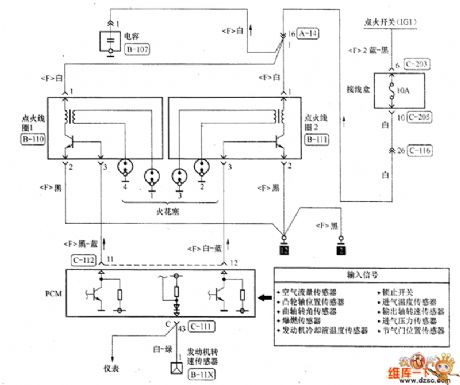
The engine ingition system circuit diagram is as shown, this engine has two ignition coils, the ignition coil 1 isused by 1 vat and 4 vat, the ignition coil 2 isused by 2 vat and 3 vat, because the 1 vat and 4 vat do not work at the same time, so the ignition coil 1 does not work. The ignition switch is cut off, the porous plug of two ignition coils are pulled down, then the ignition switch is turned on, a test lamp is adopted to measure(when it detects the power supply circuit, it should use test lamp to detect).
(View)
View full Circuit Diagram | Comments | Reading(619)
Honda Accord 2.3L car electric seat circuit principle diagram
Published:2011/5/12 22:20:00 Author:Nicole | Keyword: Honda Accord, 2.3L car, electric seat
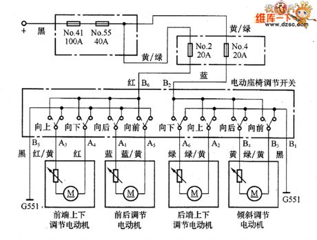
The anode wire(black) which comes from power supply pass the o. 41 fuse (100A) and the No. 55 fuse (40A) of the motor fuse/relay box, then it passes two parallel separate circuit and the No. 2 fuse (20A) and No. 4 fuse (20A) of the fuse/relay box under co-pilot side instrument panel, it came into electric seat regulation switch. When the switch is in one of adjustment state, the current flows to the relevant adjustment motor by switch contact, it drives motor to work, then it achieve adjustment, at last, the loop is completed by B5, B1 ground. (View)
View full Circuit Diagram | Comments | Reading(1404)
Shanghai GM Regal 2.0L throttle position sensor connector terminal and connecting circuit diagram
Published:2011/5/12 22:15:00 Author:Nicole | Keyword: Shanghai GM Regal, throttle, position sensor, connector terminal
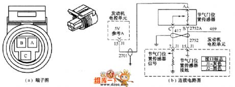
When the throttle is closed, the output voltage is lower, when the throttles are all open, the output voltage is higher than 4.0V. The electronic control unit calculates the fuel supply quantity, ignition timing, idle speed, exhaust gas recirculation, fuel evaporation emission control and air conditioner disconnection control according to throttle opening signal. The sensor connector terminal and connecting circuit is shown as below.
①Checking power voltage. The ignition switch is opened, the voltage between measuring terminal A and ground is 5V. ②Checking sensor's turning situation. The sensor terminal B and ground should be turned on.
(View)
View full Circuit Diagram | Comments | Reading(602)
Shanghai GM Regal 2.0L oxygen sensor connector terminal and connecting circuit diagram
Published:2011/5/12 22:14:00 Author:Nicole | Keyword: Shanghai GM Regal, 2.0L oxygen sensor, connector terminal
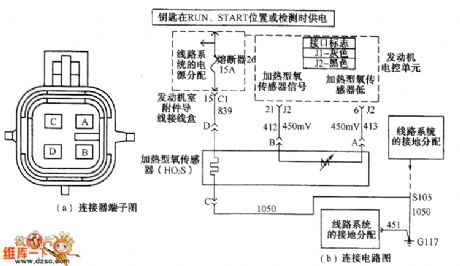
The oxygen sensor is fixed in exhaust manifold, the sensor's signal voltage inputs ECM, according to the input singal voltage, ECM can identify the oxygen content of exhaust pipe. When the mixture is thin, then the oxygen content is high, the sensor outputs about 0.1V low level; when the mixture is thick, the oxygen content is low, the sensor outputs about 0.9V high level. The oxygen sensor singal voltage changes between 0.1~0.9V, ECM will modify the fuel injection quantity according to the oxygen sensor singal.
(View)
View full Circuit Diagram | Comments | Reading(956)
The hardware circuit diagram of AC voltage measuring module system
Published:2011/5/12 0:35:00 Author:Nicole | Keyword: AC voltage, measuring module, hardware

VREF's value is adjusted by potentiometer R92, the voltage is improved to 2V, after the AC input voltage with 2V amplitude is rised, it outputs 0~4V monopolar voltage. In order to ensure thatthe sample voltage can reflect the analog signal adequately, it should has enough sampling numbers in a power frequency cycle, the sampling numbers are decided by sampling theory and the considered harmonic number.
A 220V/8V transformer changes 220V network voltage into 8V AC voltage, a 470Ω partial pressure potentiometer is connected to it, then it can be adjusted to AC voltage with 2V amplitude, after improving, the circuit is transfered into a 0~4V monopolar voltage singal.
(View)
View full Circuit Diagram | Comments | Reading(2514)
Dark room hand touch control circuit
Published:2011/5/17 2:36:00 Author:Nicole | Keyword: dark room, hand touch

Two helical or mesh electrodes with 1.58mm spacing are fixed in the bulb table or any other convenient places in dark room, when the hand touches the electrode one time, the 180W bulb turns on, if the hand touches it again, the bulb will turn off.
The AC power is changed into DC power by rectifier diode GE504A, it is fed to Q1, Q2. When the hand touches mesh electrode, the Q1 base circuit is turned on, then Q1 is conduction, Q2 turns off, in the positive half cycle of AC power, SCR turns on, 180W bulb is lightened, L1 6W small bulb is lightened too, L1 illuminates Q1, it keeps Q1 conductive, Q2 is turned off, although the hand has been left the electrode, the bulb is still shining.
If your hand touches mesh electrode again, then Q1 base turns on, the carrier which is produced by L1 shining on Q1 will be released from R6, R7, then Q1 is cut off, Q2 is turned on, SCR is not turned on, 180W and 6W bulbs are all died out. (View)
View full Circuit Diagram | Comments | Reading(526)
MCP component(MMl521XV) internal structure block diagram and its protection circuit
Published:2011/5/13 4:22:00 Author:Nicole | Keyword: component, internal structure

MCP is a multi- package produce which puts the integrated protection circuit and charge-discharge control into the same package. The internal structure block diagram is as below:
(View)
View full Circuit Diagram | Comments | Reading(592)
MOS image sensor oscilloscope imaging circuit
Published:2011/5/13 4:21:00 Author:Nicole | Keyword: MOS, image sensor, oscilloscope
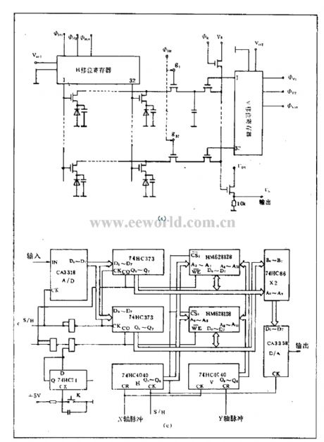
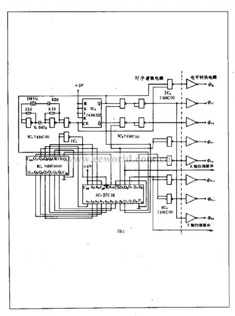
MOS image sensor is also called self scanning photodiode(SSPD), it is a solid image sensor in the late1960's. It is composed of some photodiodes, multiway MOS switch tube and scanning circuit which is integrated in a single crystal silicon. This device is divided into area array and linear array. MOS image sensor oscilloscope imaging circuit is suitable for the area devices with 32(H)×32(V) efficiency pixel. This circuit consists of temporal logic, level conversion circuit, preamplifier, sampling/maintenance and clamp circuit, A/D, D/D conversion circuit, latching storage circuit, image reduced circuit, power amplifier circuit, X, Y axis scanning circuit. The internal structure(a), surrounding drive circuit(b) and video signal processing circuit(c) are as below.
(View)
View full Circuit Diagram | Comments | Reading(1351)
LM317T application circuit
Published:2011/5/13 4:17:00 Author:Nicole

LM317T can be used to make adjustable regulated power supply, the load is often damaged due to the potentiometer's poor contact lead to voltage rise. If a triode is added(As shown in the figure), under normal circumstances, T1's base level is 0, T1 cuts off, it has no influence on circuit; when the W1 is poor contact, T1's base level rises, when it rises to 0.7V, T1 turns on, LM317T's adjustment terminal voltage drops, output voltage drops too, it can protect the load. If the triode is removed and the W1 middle point connecting line is cut off, 3.8V bulb will be burned down immediately, the output voltage reaches 21V. If it is added T1, the brightness of bulb will reduce, then LM317T output voltage is only 2V, it can effectively protect the load.
(View)
View full Circuit Diagram | Comments | Reading(1097)
Flashing alarm circuit
Published:2011/5/13 3:59:00 Author:Nicole | Keyword: Flashing alarm

When somebody touches the safety cabinet or other protected metallic objects, in order to obtain the toucher's photo, sensor circuit will input a pulse to the input terminal of this alarm circuit, its positive edge will start the semiconductor SCR rectifier and flashtube GE to work, then to drive the video camera to work. (View)
View full Circuit Diagram | Comments | Reading(495)
Municipal electric power over-voltage, under-voltage automatic indication protection circuit
Published:2011/5/13 3:56:00 Author:Nicole | Keyword: municipal electric power, over-voltage, under-voltage

When the municipal electric power is higher than the upper limit which is set by W1, LED2 is lightening, gate 2 is latched, outputing 1 , J pulls in, NC contact cuts off, to fulfill the purposes of power-off protection. When mains supply is lower than the lower limit value set by W2, gate 4 opens, LED1 is on, gate 3 outputs 0 , then J pulls in, it also can protect current failure. (View)
View full Circuit Diagram | Comments | Reading(507)
Computer Mainboard Circuit 440GX_36
Published:2011/7/6 19:55:00 Author:zj | Keyword: Computer Mainboard

View full Circuit Diagram | Comments | Reading(456)
Practical USB interface lithium ion battery charger circuit(LTC4053 as controller)
Published:2011/5/13 3:57:00 Author:Nicole | Keyword: USB interface, lithium ion battery, controller, charger

View full Circuit Diagram | Comments | Reading(556)
Computer Mainboard Circuit 440GX_38
Published:2011/7/6 19:55:00 Author:zj | Keyword: Computer Mainboard

View full Circuit Diagram | Comments | Reading(462)
LM7809-three terminal fixed steady voltage integrated circuit diagram
Published:2011/5/16 3:03:00 Author:Nicole | Keyword: three terminal, fixed steady voltage

LM7809 is a three terminal fixed steady voltage integrated circuit which is produced by National Semiconductor Corporation, it can steady the input voltage to 9V, then it can provide the related circuits with it. It also can be applied to audio and video equipments, computer, display and all kinds of electrical appliances.
The pin function and data of LM7809 integrated circuit is shown in the table1, it is actually measured from Changhong ICN-l5 movement color television.
(View)
View full Circuit Diagram | Comments | Reading(533)
| Pages:1503/2234 At 2015011502150315041505150615071508150915101511151215131514151515161517151815191520Under 20 |
Circuit Categories
power supply circuit
Amplifier Circuit
Basic Circuit
LED and Light Circuit
Sensor Circuit
Signal Processing
Electrical Equipment Circuit
Control Circuit
Remote Control Circuit
A/D-D/A Converter Circuit
Audio Circuit
Measuring and Test Circuit
Communication Circuit
Computer-Related Circuit
555 Circuit
Automotive Circuit
Repairing Circuit