Control Circuit
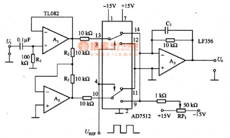
The synchronous wave detection circuit of full method
Published:2011/7/17 21:02:00 Author:Borg | Keyword: synchronous, wave detection circuit | From:SeekIC

In the figure is the synchronous wave detection circuit of full method. In the circuit, A1 and A2 can compose the balance output circuit of forward/backward phase output, even when the R2/R3 ratio is 1. the analog switch AD7512 plays an important role, the figured connector position is the inverting input terminal of the forward output(A1 output is the forward hemi-cycle of the input signal) linking to A3; if the connector is lower, the inverting output (A2 output is the backward hemi-cycle) is conducting. Considering the period of an input signal in the way, A3 output terminal can get a full-wave output.
Reprinted Url Of This Article:
http://www.seekic.com/circuit_diagram/Control_Circuit/The_synchronous_wave_detection_circuit_of_full_method.html
Print this Page | Comments | Reading(3)

Article Categories
power supply circuit
Amplifier Circuit
Basic Circuit
LED and Light Circuit
Sensor Circuit
Signal Processing
Electrical Equipment Circuit
Control Circuit
Remote Control Circuit
A/D-D/A Converter Circuit
Audio Circuit
Measuring and Test Circuit
Communication Circuit
Computer-Related Circuit
555 Circuit
Automotive Circuit
Repairing Circuit
Code: