Remote Control Circuit
Index 30
Circuit Of Infrared Ray Remote Control To Discolor
Published:2011/4/21 6:27:00 Author:Christina | Keyword: Infrared Ray, Remote Control
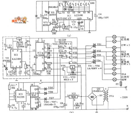
The Circuit Of Infrared Ray Remote Control To Discolor is as shown:
(View)
View full Circuit Diagram | Comments | Reading(775)
Ultraprecision long delay circuit
Published:2011/4/6 4:06:00 Author:Nicole | Keyword: long delay, ultraprecision
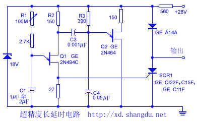
It has no need of electrolytic great timing capacitor, then can get a delay of 0.3ms to 3min, it uses steady low loss paper medium or polyester film capacitor, it also can reduce the peak current of timing unijunction transistor(Q1), so the gird resistance R1 can be replaced by large resistance.
(View)
View full Circuit Diagram | Comments | Reading(654)
New Solution 2 in 1 remote control circuit NOKIA and PHILIPS
Published:2011/4/20 3:55:00 Author:Rebekka | Keyword: remote control circuit, New Solution, NOKIA and PHILIPS
View full Circuit Diagram | Comments | Reading(1346)
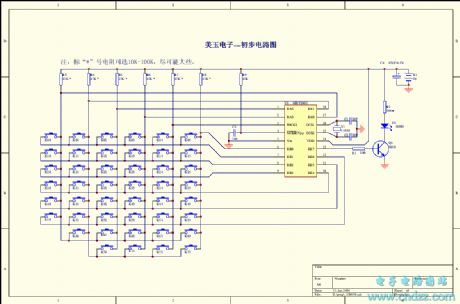
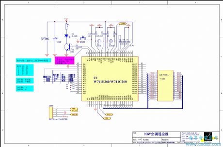
TCL Air conditioning remote control circuit
Published:2011/4/20 3:47:00 Author:Rebekka | Keyword: Air conditioning , remote control circuit
View full Circuit Diagram | Comments | Reading(2449)
Composed of TX-2 and RX-2 four-channel wireless remote control toy car circuit diagram
Published:2011/4/21 3:46:00 Author:Rebekka | Keyword: four-channel , wireless remote control, toy car
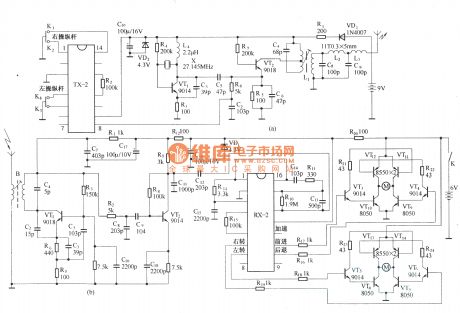
HS101/HS201 are a pair of tiny radio transceiver components. The working frequency is 280MHz. It is suitable for digital signal transmission. The control distance is 30 ~ 100m. All the components including the antenna are packaged in one. It is easy to use. The four-channel remote control switch circuit composed of HS101/HS201 is shown as below. (View)
View full Circuit Diagram | Comments | Reading(3763)
Composed of S&P27A/S&P278 long-distance remote control switch circuit diagram
Published:2011/4/21 1:11:00 Author:Rebekka | Keyword: remote control switch
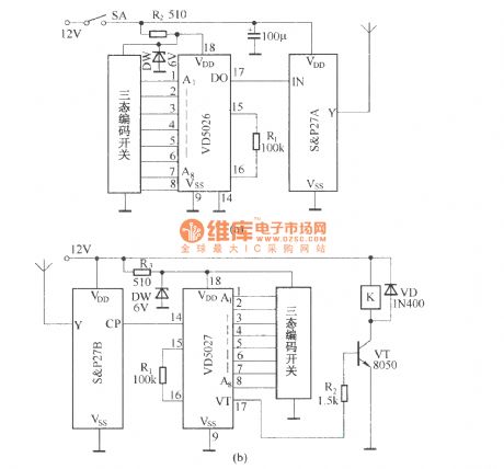
(a) shows the remote control transmitter circuit. The circuit uses the digital coding circuit VD5026 as address encoder. It uses encoding a three-state. It can be composed of multiple extensions (based on the need to launch an extension or as a receiver as the extension). (b) shows the receiver circuit, which consists of components and decoding circuit to receive and relay K VD5027 composition.
(View)
View full Circuit Diagram | Comments | Reading(2663)
Composed of S&P27A/S&P27B radio-controlled explosive device circuit diagram
Published:2011/4/21 1:06:00 Author:Rebekka | Keyword: Radio-controlled explosive device
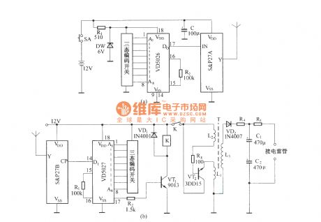
In the exploitation of mines and blasting of rock material. It is more flexible to use radio remote control detonation than wire control. And it is more reliable and economy. The figure shows the radio remote control of components of S & P27 radio-controlled detonator to detonate detonation device.
(A) is a radio remote control transmitter circuit; (b) is a radio receiver and demodulation circuit. (View)
View full Circuit Diagram | Comments | Reading(1998)
Composed of T630 and T631 wireless mini remote control circuit diagram
Published:2011/4/21 1:24:00 Author:Rebekka | Keyword: wireless mini remote control
View full Circuit Diagram | Comments | Reading(1276)
Composed of T630/T631 long-wave wireless remote control circuit diagram
Published:2011/4/21 1:22:00 Author:Rebekka | Keyword: long-wave wireless remote control
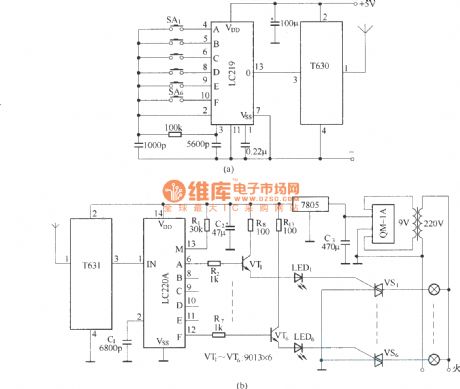
The circuit uses the long-wave wireless transceiver T630/T631, controlled 6-channel load. The features are low-power, high anti-interference ability and simple structure etc. (View)
View full Circuit Diagram | Comments | Reading(2182)
Circuit Diagram of TX05D Infrared Remote Control Light
Published:2011/4/21 1:21:00 Author:Tina | Keyword: Infrared, Remote Control
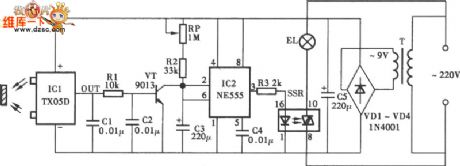
The Circuit Diagram of TX05D Infrared Remote Control Light is as shown.
(View)
View full Circuit Diagram | Comments | Reading(1452)
Circuit Diagram of KA2184 Infrared Ray Remote Control Light
Published:2011/4/21 1:23:00 Author:Tina | Keyword: Infrared Ray, Remote Control
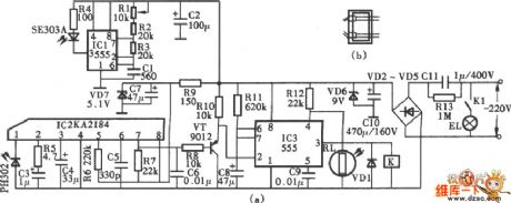
The Circuit Diagram of KA2184 Infrared Ray Remote Control Light. (a) Circuit Diagram; (b) installation diagram is as shown:
(View)
View full Circuit Diagram | Comments | Reading(1271)
Long-range Infrared Ray Remote Circuit
Published:2011/4/21 1:00:00 Author:Tina | Keyword: Long-range, Infrared Ray, Remote Circuit
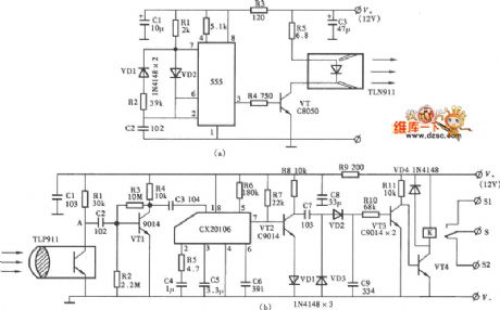
The Long-range Infrared Ray Remote Circuit is as shown:
(View)
View full Circuit Diagram | Comments | Reading(1320)
Electronic Fly Disinfestation Circuit
Published:2011/4/20 9:58:00 Author:Robert | Keyword: Fly Disinfestation
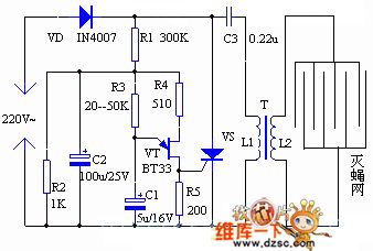
Electronic Fly Disinfestation Circuit as shown below:
Welcome to reprint, information come from Weiku Electric Market Website (www.seekic.com) (View)
View full Circuit Diagram | Comments | Reading(982)
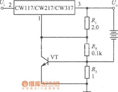
Current limit protection charger circuit with CW117
Published:2011/4/20 3:21:00 Author:Jessie | Keyword: Current limit protection, charger
View full Circuit Diagram | Comments | Reading(619)
Fans imitating natural wind control circuit with CD4541
Published:2011/4/19 22:22:00 Author:Jessie | Keyword: Fans imitating natural wind control
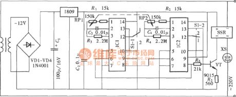
In fact, fans imitating natural wind control circuit is a kind of open/stop time transforms cycle timing controller. This control circuit makes fans when open and stop by suitable choice of electric fans' open and stop time.So that itsimulates the similar state of natural wind to make person feel both cool and comfortable. Its composition is as shown. IC1 and IC2 are CD4541. (View)
View full Circuit Diagram | Comments | Reading(1969)
Adjustable multi-function timing controller circuit
Published:2011/4/19 22:57:00 Author:Jessie | Keyword: Adjustable, multi-function, timing controller
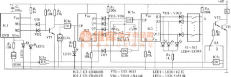
This circuit first makes seconds time base form mimute signalby the multi-stage separate frequency. After multi-stage separate frequency, mimute signalis output as binary combination classification. By the switch controlling, we can preset timing open or timing shut these two working states. This circuit has high control accuracy, and the circuit component is as shown. (View)
View full Circuit Diagram | Comments | Reading(711)
Long time delay timing circuit with CD4541
Published:2011/4/19 22:43:00 Author:Jessie | Keyword: Long time delay, timing
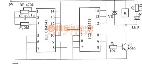
The two pieces of CD4541 can compose a long time delay timing circuit. Its delay time can reach 10 h, even several days or months. Its composition is as shown. (View)
View full Circuit Diagram | Comments | Reading(6038)
Adjustable circulating timing controller circuit
Published:2011/4/19 22:53:00 Author:Jessie | Keyword: Adjustable, circulating timing controller
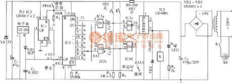
The timing controller uses the LCD's minute signals. After the combination oftwo level separate frequency circuit, it can build a multi-level timing control function. It composes single timing open/shut or automatic cycle working mode by the control switch. Control time from1 ~ 90min is adjustable. Circuit's components areas shown. (View)
View full Circuit Diagram | Comments | Reading(897)
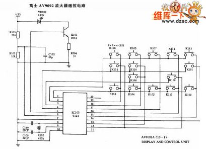
KONES AV9092 amplifier remote control circuit
Published:2011/4/2 4:16:00 Author:may | Keyword: KONES, amplifier, remote control
View full Circuit Diagram | Comments | Reading(1101)
Single junction transistor controllable pulse generator circuit
Published:2011/4/18 22:45:00 Author:Jessie | Keyword: Single junction transistor, controllable pulse generator
View full Circuit Diagram | Comments | Reading(793)
| Pages:30/34 At 202122232425262728293031323334 |
Circuit Categories
power supply circuit
Amplifier Circuit
Basic Circuit
LED and Light Circuit
Sensor Circuit
Signal Processing
Electrical Equipment Circuit
Control Circuit
Remote Control Circuit
A/D-D/A Converter Circuit
Audio Circuit
Measuring and Test Circuit
Communication Circuit
Computer-Related Circuit
555 Circuit
Automotive Circuit
Repairing Circuit
