
Remote Control Circuit
Index 26
Pulse dialing nine-channel infrared remote control circuits of the LR40992 and μPC1373
Published:2011/5/11 18:50:00 Author:TaoXi | Keyword: Pulse dialing, nine-channel, infrared remote control
The transmitter circuit:
The receiver circuit: (View)
View full Circuit Diagram | Comments | Reading(584)
infrared remote control energy-saving delay switch principle and circuit
Published:2011/5/11 9:00:00 Author:Christina | Keyword: infrared remote control, energy-saving, delay switch, principle

This circuit is composed of the infrared receiving demodulation integrated circuit CX20L06 and NE555, and it uses the bidirectional thyristor as the light switch. This circuit is one kind of integrated infrared remote control switch circuit, the composition is as the figure shown.
(View)
View full Circuit Diagram | Comments | Reading(1135)
Radio remote control car sending schematic diagram
Published:2011/5/11 1:36:00 Author:Rebekka | Keyword: Radio remote control car

Here is the diagram of Radio remote control car sending schematic. (View)
View full Circuit Diagram | Comments | Reading(5365)
BU5814FT1 monolithic remote control transmitter integrated circuit
Published:2011/5/10 1:16:00 Author:Fiona | Keyword: monolithic remote control transmitter


BU5814FT1 is a monolithic remote control transmitter integrated circuit.It's widely used in various remote control systems, such as DVD players, televisions, audio equipment.
1.Features
BU5814FT1 contains the keys scan pulse generator integrated circuit, the remote control command encoder, emission signal buffer amplifier circuit, transmitting the signal buffer amplifier circuit, test circuit, the user code setting circuit, and other ancillary circuit.
2.pin functions and data
BU5814FT1 integrated circuit uses 22-pin dual in-line package.The pin functions and data are shown in Table 1.
Table 1 BU5814FT1 integrated circuit's pin functions and data
3.Typical application circuit
The infrared remote control transmitter's typical application circuit which is posed by the BU5814FT1 integrated circuit is shown in Figure 1.
Figure 1 the typical application circuit of the BU5814FT1 integrated circuit
Tip: to determine whether the remote control transmitter IC is damaged, it's available to use multimeter to test the potential of BU5814FT1 (19) feet.Whether the potential has a small jump. If has,it is illustrated that there has coded pulse signal output from the output,the integrated circuit is working properly;on the contrary,the integrated circuit is damaged,it need to replace a new integrated circuit. (View)
View full Circuit Diagram | Comments | Reading(1172)
BU-3762AF monolithic remote control transmitter integrated circuit
Published:2011/5/10 1:17:00 Author:Fiona | Keyword: monolithic remote control transmitter


BU-3762AF is a monolithic remote control transmitter integrated circuit.It’s widely used in various remote control systems, such as televisions, audio equipment, DVD players and so on.
1. Features
BU-3762AF integrated circuit includes scan keys pulse generator, telecommand encoder, clock oscillation circuit, transmit signal pre-amplifier circuit, test circuit, and other ancillary circuit.
2. pin functions and data
BU-3762AF integrated circuit uses 18-pin dual in-line package.The main pin function as follows:② feet: reset control signal input, high reset.④ - (14) feet: constitute the keyboard matrix circuit used for manual operation.(15) feet: remote control command signal output, the output signal promotes the infrared emitting diodes infrared light after being amplified by the driver tube VT1 (17), (16) feet: the side external components of clock oscillation circuit.(18) feet : the supply voltage input.the working parameters of BU-3762AF integrated circuit is listed in Table 1.
Table 1 the working parameters of BU-3762AF integrated circuit
3. Typical application circuit
The typical application of the remote control circuit consisting of BU-3762AF integrated circuitisshown in Figure 1.
Figure 1 typical application of the remote control circuit consisting of BU-3762AF integrated circuit
(View)
View full Circuit Diagram | Comments | Reading(817)
The ultrasonic remote control switch circuit with the infrared remote control mode
Published:2011/5/10 22:36:00 Author:Christina | Keyword: ultrasonic, remote control switch, infrared remote control

The sub-ultrasonic remote control switch always uses the relay to control the load, and this device has some points of features such as the good load capacity, wide range of applications, low price (6 RMB each), families have a lot of this device. But there is also a weak point: short life of the balloon rubber which can produce the sub-ultrasonic, and this balloon rubber is easy to lose. So we use the TV or VCD's infrared remote controller to control it. The principle and modification method are:
The sub-ultrasonic remote control switching circuit is as shown in the figure, the circuit in the dashed box is the modified circuit, the 220V AC main-voltage is limited and steped down by the C1, the D1~D4 output the DC voltage of about 15V, and this voltage is limited by R2 then supplies to the relay control circuit. XD is the piezoelectric ceramic, the sub-ultrasound is amplified by BG1 and selected by L, C3 and then is amplified by BG2 to trigger the bistable circuit to flip through C6 and C7.
(View)
View full Circuit Diagram | Comments | Reading(852)
SCR stepless light-adjustment and speed-adjustment (two-way) circuit
Published:2011/5/10 22:33:00 Author:Christina | Keyword: SCR, stepless, light-adjustment, speed-adjustment, two-way

View full Circuit Diagram | Comments | Reading(872)
Temperature protection circuit working in the AC grid
Published:2011/5/9 20:31:00 Author:TaoXi | Keyword: Temperature protection, AC grid

It is very dangerous that many devices are working with the over-allowable temperature, so we must set the protection circuit. The thermistor showes the low resistive in lower temperature. With the increasing of temperature, it's resistance increases in proportion. The final resistance can be up to several megohms. If we add the thermistor between the two-way SCR's cathode and anode to let the two-way SCR connects to the 220 AC power supply through the load, so in the normal temperature, the two-way SCR will be trig whenever the voltage is over-zero, at this time, the SCR is equivalent to the entire conduction, and the load gets the power. Otherwise, if the outside temperature exceeds the rated temperature, the thermistor will be high resistive, the so that the thyristor is not conduction any more to cut off the load circuit. (View)
View full Circuit Diagram | Comments | Reading(811)
Simple Additional Remote Control Circuit(LM555、CD4017) of Color TV
Published:2011/5/10 1:59:00 Author:chopper | Keyword: Remote Control, Color TV

View full Circuit Diagram | Comments | Reading(1070)
Adjustable general time relay (NE555, CD4013) circuit
Published:2011/5/9 22:53:00 Author:Christina | Keyword: Adjustable, general, time relay

The multifunction of this circuit means it has three operating modes: the delay picking function , the delay releasing function and the delay looping function . The delay picking function means after the pre-boot, the relay will not close. Only when it is the scheduled time, the relay will close. The delay releasing function is the opposite of the delay picking function , after the pre-boot, the relay closes, when it is the scheduled time, the relay will release. The two operations are throwaway, when the relay completes a working process, the control part of the circuit gets into the stable state. The delay looping function is: the circuit will be running with the pre-open interval time and the pre-stop interval time, and it will not stop until you cut off the power or change the working condition. The circuit is as shown.
(View)
View full Circuit Diagram | Comments | Reading(2877)
DTMF infrared remote control circuit
Published:2011/5/10 18:51:00 Author:Christina | Keyword: DTMF, infrared, remote control

The DTMF infrared remote control circuit. The DTMF encoded signal can be decoded by the special decoder and the PLL audio decoder LM567. But the DTMF encoded signal which is decoded by only one decoder, has only one frequency, one group of control signal is composed by two decoder's output frequency. The infrared remote control signal which is produced by the DTMF launcher is as shown, one channel of the control signal's infrared remote control switch is decoded by two LM567. And this circuit is composed of the twelve channels DTMF coding infrared remote control launcher, the infrared receiving voltage amplifier, the channel signal decoder, the switch controller and the driving circuit.etc.
(View)
View full Circuit Diagram | Comments | Reading(3360)
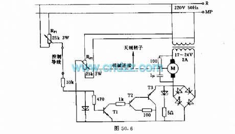
Ventilation motor temperature control circuit
Published:2011/5/9 22:00:00 Author:TaoXi | Keyword: Ventilation motor, control circuit

Related components PDF download:
BC261BC107B
This circuit can be used to control the electrical insulation heating device. The sensor uses the 100kΩ thermistor. And this sensor controls the shaded pole motor running fast or running slow or stop running. The SCR's (which controls the motor's open telegram or power outage) trigger pulse is discharged by the transistor which is controlled by the temperature bridge circuit. Once the capacitor's charging voltage reaches the turn circuit's (compose of the transistor) turn voltage, the SCR will conduct and the motor starts working, the capacitor starts discharging. We control the voltage which is added on the ventilation motor according to the sensor's temperature and the time of the half-cycle conduction, to achieve the ratio adjustment.
(View)
View full Circuit Diagram | Comments | Reading(1369)
MN6030B Remote Control Transmitter Circuit
Published:2011/5/9 1:13:00 Author:Sharon | Keyword: Remote Control Transmitter


MN6030B is Panasonic's remote control transmitter IC.It'swidely used in TV, DVD player, audio remote control system, like Panasonic series of color TV sets.1. Features MN6030B integrated circuit includes timing pulse generator, key encoder, binary counter, modulation converter, flutter, double bonds oscillation preventing circuit and clock circuit.The block diagram of the circuit and typical application circuit are as shown.2. Pin functions and data MV6030B's (8) ~ (21) feet is the input and output pins of key scan signal, (4) and (5) feet are external clock oscillator components, (6) output pins for the transmit signal, (1) ~ (3) feet to power, (2) foot grounded, (7) feet at the end use.WN6030B IC is sealed with 22 feet dual in-line package, and its operating parameters are listed in Table.3. Typical application circuit Typical application of remote control Transmitter made by M6030B integrated circuits is shown in the Figure below.The circuit is used in Panasonic color television series.
(View)
View full Circuit Diagram | Comments | Reading(1694)
Short-circuit protector with the relay
Published:2011/5/9 20:35:00 Author:TaoXi | Keyword: Short-circuit protector, relay
Related components PDF download:
A1S1SC945 (View)
View full Circuit Diagram | Comments | Reading(669)
Temperature window overrun alarm circuit
Published:2011/5/9 19:17:00 Author:TaoXi | Keyword: Temperature window, overrun alarm

Related components PDF download:
MAX6502MAX6504HFC5212TDA2822
As the figure shown, this circuit is composed of the high-limit & low-limit temperature detecting circuit, the voice circuit, the audio amplifier circuit and the AC step-down rectifier circuit.etc. The high-limit temperature monitor uses the temperature switch IC MAX6502 to monitor, it can transform the monitored object's temperature into the electric signal, if the signal voltage exceeds the set threshold temperature such as 55 degrees celsius, the monostable trigger will output the shaped pulse to promote the output stage outputs the high-level voltage control signal. This signal adds to the voice circuit IC3's trigger port TG through VD1, to trig the sound. (View)
View full Circuit Diagram | Comments | Reading(1021)
Satellite receiver antenna servo control circuit
Published:2011/5/9 19:30:00 Author:TaoXi | Keyword: Satellite receiver, antenna servo, control circuit
In the figure, potentiometer Rp2's sliding contact-point axis is connected with the antenna axis. Only when the Rp1 and Rp2 point at the same position, the transistors will not turn on, and the rectifier bridge will close, there is no voltage on the motor, so the antenna is not moving, Otherwise, the antenna or motor will synchronously turn with the given potentiometer. (View)
View full Circuit Diagram | Comments | Reading(3258)
Temperature control circuit with the temperature range of -10℃ to 20℃
Published:2011/5/9 19:51:00 Author:TaoXi | Keyword: Temperature control, temperature range

Related components PDF download:
TCA965BC327BCW80
This circuit can be used to adjust the temperature of room or container. It uses the thermistor K274S1 (with the metal shell) as the sensor, and it can be used in the air or liquid. The amplifier circuit is assumed by the window discriminator TCA965 and the rear PNP transistor. By designing the input divider, we can observe the cut-off point of the sensor, when you cut off it, the yellow LED will turn on, and the relay will release.
If the temperature is too low, the relay will turn on (red LED turns on), we can heat the 2x1.5kW equipment by using the relay, the given temperature is adjusted by the potentiometer R.
Main technical data:
Operating voltage: 220VDC supply voltage: 12VRelay max current: 200mARelay turn-on temperature: -10 ℃ to +25 ℃Hysteresis width: max 15mV (equivalent to 1 ℃)Relay connection equipment power: 2x1.5kW (View)
View full Circuit Diagram | Comments | Reading(1112)
Temperature control circuit
Published:2011/5/9 20:08:00 Author:TaoXi | Keyword: Temperature, control

Related componts PDF download:
BC251ABC107BBC141
In figure (a), heating resistor RL connects to the 220V AC grid by the SCR. Figure (b) shows the control circuit. In order to measure the temperature, we use the bridge circuit which is composed of the resistance RT (measuring head), R (the given value resistor) and two 1.5kΩ resistors.
When the value of probe resistance is the same as the resistance R, the bridge is in balance. The probe current is about 10mA.
The resistance number of the transformer: n1 and n2: 100 turns, n3 and n4: 80 turns, they are all surrounded by the 0.2mm copper-paint wire. (View)
View full Circuit Diagram | Comments | Reading(1017)
The proportion of time division system remote control circuit diagram
Published:2011/5/9 0:59:00 Author:Rebekka | Keyword: Remote control system , proportional division


The proportion of time division system remote code transmission circuit:
The proportion of time division system remote control receiver decoding circuit:
(View)
View full Circuit Diagram | Comments | Reading(836)
temperature alarm circuit
Published:2011/5/9 19:17:00 Author:TaoXi | Keyword: temperature, alarm
Related components PDF download:
TAA3761TAA2176A (View)
View full Circuit Diagram | Comments | Reading(617)
| Pages:26/34 At 202122232425262728293031323334 |
Circuit Categories
power supply circuit
Amplifier Circuit
Basic Circuit
LED and Light Circuit
Sensor Circuit
Signal Processing
Electrical Equipment Circuit
Control Circuit
Remote Control Circuit
A/D-D/A Converter Circuit
Audio Circuit
Measuring and Test Circuit
Communication Circuit
Computer-Related Circuit
555 Circuit
Automotive Circuit
Repairing Circuit