Remote Control Circuit
Index 21
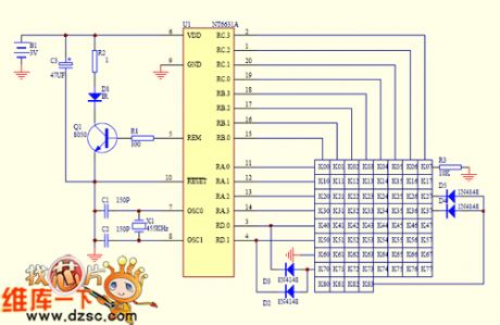
The multi-encoding single chip remote control circuit
Published:2011/6/23 10:15:00 Author:qqtang | Keyword: single chip, remote control
View full Circuit Diagram | Comments | Reading(1049)
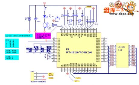
A air-conditioner remote control circuit of CL
Published:2011/6/23 10:17:00 Author:qqtang | Keyword: air-conditioner, remote control
View full Circuit Diagram | Comments | Reading(2876)
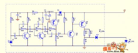
The infrared remote control signal converter circuit
Published:2011/6/23 10:12:00 Author:qqtang | Keyword: infrared, remote control, signal converter
View full Circuit Diagram | Comments | Reading(1000)
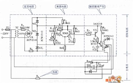
The machine tool magnetic sucker low-current protection circuit
Published:2011/6/19 2:47:00 Author:Seven | Keyword: machine tool, magnetic sucker, low-current


See as the circuit, the +24V is generated by stepping down the 110V power supply. When the touch spot JK of the magnetic sucker circuit is closed, the sucker is on and working, whose regulated current is 1.4A(the current of strong sucker is higher). At the moment, the sampling resistor which is serially connected in the electric sucker will have a 1.4v voltage drop, the dropped voltage is sampled by the potentiometer RP1 and imposed on the transistor VT1 input circuit, and then compound-magnified by VT1 and VT2. The multiple after being compounded by VT1 and VT2 is high.
(View)
View full Circuit Diagram | Comments | Reading(1043)
The ultrasonic wave remote control lamp switch working principle and circuit (1)
Published:2011/6/20 22:05:00 Author:Seven | Keyword: ultrasonic wave, remote control, working principle

The ultrasonic wave remote control lamp switch working principle and circuit (1) is shown as above:
(View)
View full Circuit Diagram | Comments | Reading(1545)
The working principle and circuit of the ultrasonic wave remote control lamp switch
Published:2011/6/20 1:17:00 Author:Seven | Keyword: working principle, ultrasonic wave, remote control lamp
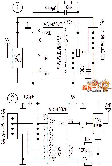
The working principle and circuit of the ultrasonic wave remote control lamp switchis shown in the figure.
(View)
View full Circuit Diagram | Comments | Reading(1387)
The practical ultrasonic wave remote control emitting circuit
Published:2011/6/20 22:05:00 Author:Seven | Keyword: ultrasonic wave, remote control
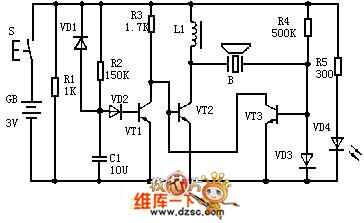
The practical ultrasonic wave remote control emitting circuit is shown in the figure.
(View)
View full Circuit Diagram | Comments | Reading(1297)
The FM modulation circuit of crystal oscillator
Published:2011/6/20 1:33:00 Author:Seven | Keyword: FM modulation, crystal oscillator

In the figure is the FM modulation circuit of crystal oscillator. FM modulation has direct and indirect FM ways, the direct FM method is to directly change the frequency of the oscillating circuit, it's simple, but as it is the LC oscillating circuit, the bias is kind of noticeable, and the stability is weak, i.e the frequency is easy to be affected by the power supply voltage change and the temperature change.
By using the crystal oscillating circuit, the frequency stability is high and the bias is only about 1%. In the circuit, X is a 10MHz crystal oscillator and it directly modulates the frequency of the circuit. (View)
View full Circuit Diagram | Comments | Reading(7407)
The practical ultrasonic wave remote control reception circuit
Published:2011/6/20 22:06:00 Author:Seven | Keyword: ultrasonic wave, remote control
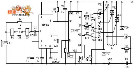
The practical ultrasonic wave remote control reception circuit is shown in the figure.
(View)
View full Circuit Diagram | Comments | Reading(1044)
The infrared remote control music outlet circuit
Published:2011/6/20 0:40:00 Author:Seven | Keyword: infrared, remote control

The infrared remote control music outlet circuit is shown in the figure.
(View)
View full Circuit Diagram | Comments | Reading(901)
The ultrasonic wave remote control lamp switch circuit
Published:2011/6/20 22:07:00 Author:Seven | Keyword: ultrasonic wave, remote control

The ultrasonic wave remote control lamp switch circuit is shown in the above figure.
(View)
View full Circuit Diagram | Comments | Reading(1903)
The lighting lamp ultrasonic wave remote control circuit
Published:2011/6/20 22:09:00 Author:Seven | Keyword: lighting lamp, remote control

The lighting lamp ultrasonic wave remote control circuit is shown as above.
(View)
View full Circuit Diagram | Comments | Reading(999)
The remote control circuit
Published:2011/6/20 22:10:00 Author:Seven | Keyword: remote control
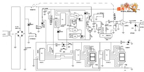
The remote control circuit is shown in the above figure.
(View)
View full Circuit Diagram | Comments | Reading(1003)
The door control lamp circuit (with the electric timer and alarm)
Published:2011/6/21 22:30:00 Author:qqtang | Keyword: door control lamp, electric timer
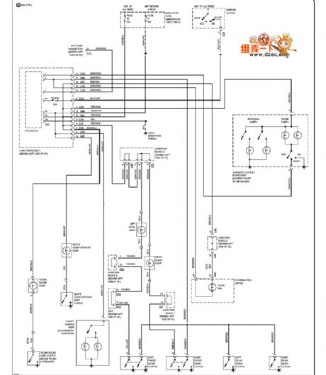
The door control lamp circuit (with the electric timer and alarm) is shown as above.
(View)
View full Circuit Diagram | Comments | Reading(939)
The color TV remote control 21 circuit
Published:2011/6/21 2:05:00 Author:Seven | Keyword: color TV, remote control
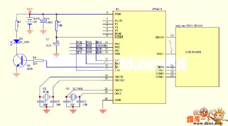
Figure: The color TV remote control 21 circuit (View)
View full Circuit Diagram | Comments | Reading(1078)
Thyristor energy consumption brake control circuit
Published:2011/6/21 8:03:00 Author:John | Keyword: Thyristor

Thyristor energy consumption brake control circuit is shown.
(View)
View full Circuit Diagram | Comments | Reading(1102)
Thyristor furnace temperature automatic control circuit
Published:2011/6/21 8:08:00 Author:John | Keyword: Thyristor, furnace
View full Circuit Diagram | Comments | Reading(1277)
The SAFl039 infrared remote control reception decoding circuit
Published:2011/6/20 21:19:00 Author:Seven | Keyword: remote control, reception

Figure: The SAFl039 infrared remote control reception decoding circuit (View)
View full Circuit Diagram | Comments | Reading(977)
The T6A2800 (TV set) infrared remote control reception circuit
Published:2011/6/20 11:17:00 Author:Seven | Keyword: infrared, remote control
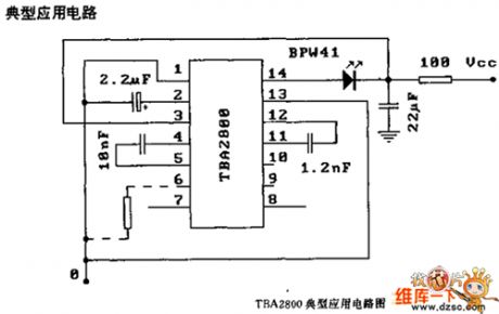
Figure: The T6A2800 (TV set) infrared remote control reception circuit (View)
View full Circuit Diagram | Comments | Reading(900)
The practical ultrasonic remote control circuit
Published:2011/6/19 10:29:00 Author:Seven | Keyword: ultrasonic, remote control

The practical ultrasonic remote control circuit is shown as follows.
figure 1. the emitting circuit (View)
View full Circuit Diagram | Comments | Reading(847)
| Pages:21/34 At 202122232425262728293031323334 |
Circuit Categories
power supply circuit
Amplifier Circuit
Basic Circuit
LED and Light Circuit
Sensor Circuit
Signal Processing
Electrical Equipment Circuit
Control Circuit
Remote Control Circuit
A/D-D/A Converter Circuit
Audio Circuit
Measuring and Test Circuit
Communication Circuit
Computer-Related Circuit
555 Circuit
Automotive Circuit
Repairing Circuit
