
Index 94
10s_USING_15_V_SUPPLY
Published:2009/7/12 21:33:00 Author:May
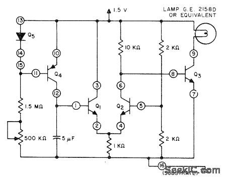
RCA CA3096E fivetransistor array drives indicator lamp thatcomes on at end of timing interval,Q5 is one of PNP transistors in array connected as diode.- Linear Integrated Circuits and MOS/FET's, RCA Solid State Division,Somerville,NJ,1977,p205-210. (View)
View full Circuit Diagram | Comments | Reading(682)
SIMULTANEOUS_CURRENT_LIMITING
Published:2009/7/19 20:53:00 Author:Jessie
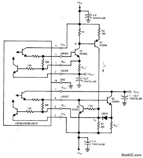
Limiting action of circuit depends on output current of positive regulator but acts simultaneously on both positive and negative outputs of National LM125 dual tracking regulator. Positive output current produces voltage drop across R1 that makesQ1conduct. When increase in current makes voltage drop across R2 equal negative current limit sense voltage, negative regulator will current-limit. Positive regulator closely follows negative output down to level of about 700 mV.Q2 turns off negative pass transistor during simultaneous current limiting. Output voltages are ±15V.- Linear Applications, Vol. 2, National Semiconductor, Santa Clara, CA, 1976, AN-82, p 12-13. (View)
View full Circuit Diagram | Comments | Reading(579)
15V_AT_5A_WITH_PROTECTION
Published:2009/7/19 20:36:00 Author:Jessie
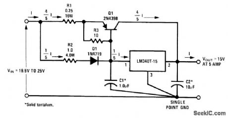
External boost transistor is used with National LM340T-15 regulator to boost output current capability to 5A without affecting such features as short-circuit current limiting and thermal shutdown. Short-circuit current is held to 5,5A. Heatsink for Q1 should have at least 4 times capacity of heatsink for IC.- Linear Applications, Vol. 2, National Semiconductor, Santa Clara, CA, 1976, AN-103,p3-4. (View)
View full Circuit Diagram | Comments | Reading(1140)
Wide_range_ratiometer_using_two_100_kHz_converters_with_less_than_a_01_error_over_a_dynamic_range_of_10000_to_1
Published:2009/7/19 20:26:00 Author:Jessie
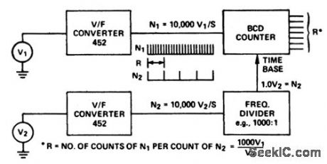
Wide-range ratiometer using two 100 kHz converters with less than a 0.1% error over a dynamic range of 10,000 to 1 (courtesy Analog Devices, Inc.). (View)
View full Circuit Diagram | Comments | Reading(426)
Notch_filter_using_two_ECG941_941D_941Ms_as_a_gyrator
Published:2009/7/19 20:11:00 Author:Jessie
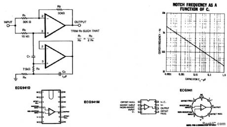
Notch filter using two ECG941/941D/941Ms as a gyrator (courtesy GTE Sylvania Incorporated). (View)
View full Circuit Diagram | Comments | Reading(674)
NOISE_CORRELATOR
Published:2009/7/17 5:03:00 Author:Jessie
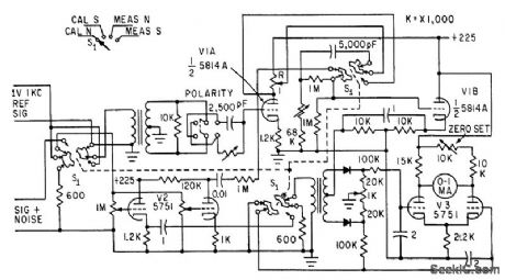
Requires two inputs, reference signal derived from modulating source and signal-pulse-noise input from receiver under test. Signal and noise components can then be measured separately. -B. T. Newman, Evaluating Radio Receiver Susceptibility to Interference, Electronics, 34:15, p 70-74. (View)
View full Circuit Diagram | Comments | Reading(584)
High_voltage_booster
Published:2009/7/17 4:56:00 Author:Jessie
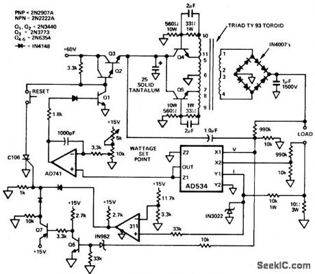
High-voltage booster. Care should be taken with this circuit because it takes 300 mW and turns it into 1000 volts at 300 watts,This is many times greater than is necessary to kill and is absolutely lethal The AD534 is used to control the output of toroidal DC-to-DC converter.Both the AD534 multiplier and the DC-to-DC converter are inside the AD741's feedback loop,The inverter frequency is 4 kHz (courtesy Analog Devices,Inc.). (View)
View full Circuit Diagram | Comments | Reading(1280)
Automatic_night_light_to_discourage_prowlers_or_burglars
Published:2009/7/17 4:53:00 Author:Jessie
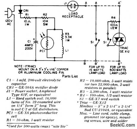
Automatic night light to discourage prowlers or burglars. One of two circuits can be built as shown in the schematic, depending on the requirements. For small loads, 15 watts, the reed switch can directly control the light (courtesy General Electric Company). (View)
View full Circuit Diagram | Comments | Reading(1781)
_15V_TRACKING__5V
Published:2009/7/17 4:42:00 Author:Jessie
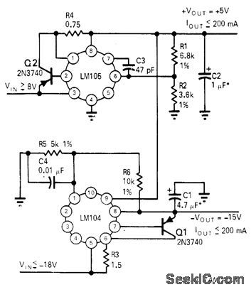
LM104 negative regulator is used with inverting gain to give negative output voltage that is greater than positive reference voltage. Noninverting input is tied to divider R5-R6 between negative output and ground. Positive reference determines line regulation and temperature drift, with negative output tracking.-R. C. Dobkin, One Adjustment Controls Many Regulators, EDN Magazine, Nov. 1, 1970, p 33-35. (View)
View full Circuit Diagram | Comments | Reading(570)
0_20_V_AT_1_A
Published:2009/7/17 4:23:00 Author:Jessie

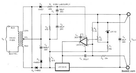
Variable-output regulated supply for lab use maintains output voltage within 2 mV of desired value for outputs up to 1 A. Arrangement uses National LM120 negative regulator as pass element, LM101A opamp as error amplifier, and LM113 zener as reference. Circuit provides complete protection against load shorts. LM120 requires adequate heatsink for continuous operation. - C. T. Nelson, Power Distribution and Regulation Can Be Simple, Cheap and Rugged, EDN Magazinq, Feb. 20, 1973, p 52-58. (View)
View full Circuit Diagram | Comments | Reading(724)
CONTINUOUS_LOOP_PLAYBACK_DEVICE
Published:2009/7/17 4:02:00 Author:Jessie
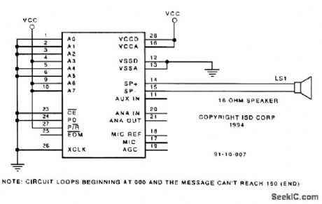
This requires a prerecorded message to be preprogrammed in the ISD1020A. If you want a message to repeat over and over again, automatically, the circuit in the figure will do the trick. It uses the Operation mode to accomplish playback looping as long as the message starts at address 0 (the beginning of the memory) and does not require the full 20 seconds of analog storage. A message is first recorded into an ISD1020A using the Yack/Yack project, with all address bits tied low. Next, connect the circuit in the figure. Note that address bits A6 and A7 are tied high to enable the Operation mode. Bit A3 is also tied high to enable continuous repeat. With PD low, P/R high, and CB held low, the beginning message in the ISD1020A will repeat. (View)
View full Circuit Diagram | Comments | Reading(783)
SOIL_MOISTURE_MONITOR
Published:2009/7/17 3:58:00 Author:Jessie
In the circuit, when R6 equals the value of the resistance of the soil between the two probes, the bridge circuit is in balance. To set up the circuit, bring the soil that you wish to monitor to the proper moisture level and insert the two probes into that soil. Then adjust R6, until the two LEDs are both off, or at least dim to the same level. The two LEDs serve as a null indicator. That is, LED2 is on when the ground resistance is higher than the preset resistance of R6, and LED1 is on when the ground resistance is lower than the preset value. When both LEDs go dark or dim to the same brilliance, the bridge circuit is in balance. At balance, R6 equals the ground resistance. The probes are two 6-inch by 1/16-inch round stainless-steel rods mounted about 1 inch apart in an insulated handle. (View)
View full Circuit Diagram | Comments | Reading(668)
60_hertz_nicad_battery_charger_with_third_electrode_sensing
Published:2009/7/17 3:45:00 Author:Jessie
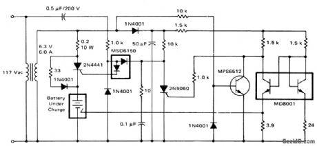
60-hertz nicad battery charger with third-electrode sensing (courtesy Motorola Semiconductor Products Inc.). (View)
View full Circuit Diagram | Comments | Reading(552)
Signal_level_envelope_detector
Published:2009/7/17 3:21:00 Author:Jessie

Signal-level envelope detector. The MC1535G is a dual op amp and the MC844P a dual power gate. This circuit indicates by way of the lamp when the input signal is out of range (courtesy Motorola Semiconductor Products Inc.). (View)
View full Circuit Diagram | Comments | Reading(1351)
NE602_IF_OUTPUT_CIRCUITS
Published:2009/7/17 2:42:00 Author:Jessie
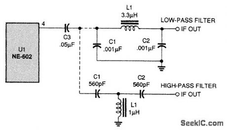
Either the low-pass filter or high-pass filter outputs can be used, depending on the situation. (View)
View full Circuit Diagram | Comments | Reading(706)
NONDIFFERENTIAL_MAGNETIC_INVERTER_1
Published:2009/7/17 1:47:00 Author:Jessie

Is analogous to free-running capacitor-coupled mvbr. Frequency and output amplitude are both directly proportional to input voltage. Chief drawback is need to increase input voltage to get higher frequency, which in turn increases all winding voltages.-J. Markus, Handbook of Electronic Control Circuits, McGraw-Hill, N.Y., 1959, p 102. (View)
View full Circuit Diagram | Comments | Reading(552)
FREQUENCY_PROBE
Published:2009/7/17 1:47:00 Author:Jessie
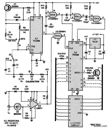
This design is a simplified 3 1/2-digit frequency counter with four ranges: 2000 Hz, 20.00 kHz, 200.0 kHz, and 2.000 MHz. An effort was made to miniaturize the circuit so that it would fit in a standard logic-probe-type case; the complete circuit was assembled on a perforated board cut down to 1×4 3/4 inches. The normal crystal time base with all its dividers was eliminated in favor of one eight-pin DIP: IC1, a TLC555 CMOS oscillator. It provides gate timings of 1000 ms, 100 ms, 10 ms, and 1 ms using R1, R2, C1, and C2 as the crucial timing components, Select C1 to be exactly 1/10 the value of C2. Calibration is done with trimmer potentiometer R5. Integrated circuit IC2 (an LM311) provides input conditioning for any waveform of ±0.9 to ±30 V, whether triangle, sine, or square wave. Integrated circuit IC4 (a CD4011 or 74C00) provides proper pulse delays to IC3, a 74C928 3 1/2-digit counter chip that directly drives a miniature 3 1/2- or 4-digit, common-cathode LED display. The digit drivers shown, Q2 to Q5 and R20 to R23, can be replaced with a single DIP package (such as a 7549, 75492, etc.). A 78 regulator, IC5, provides the +5 V for the circuit, and is mounted on the board with the other components. It can be driven externally via a standard ac wall adapter of 7 to 12 V at 30 mA, or from a 9-V battery. Be sure to bypass the supply pins on each IC with a 0.1-μF monolithic capacitor for noise-free performance. When accuracy is important, a crystal-controlled time base should be used. (View)
View full Circuit Diagram | Comments | Reading(1354)
MODEM_PROTECTION_CIRCUIT
Published:2009/7/17 2:32:00 Author:Jessie
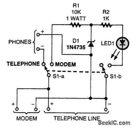
A common problem in modem communications is that family members often pick up extensions during a modem call. Forget about having your downloads messed up by someone lifting a phone.This circuit completely disconnects all phones on a line when you are using a modem. (View)
View full Circuit Diagram | Comments | Reading(565)
POWER_SUPPLY_PASS_TRANSISTOR_PROTECTION_CIRCUIT
Published:2009/7/17 2:31:00 Author:Jessie
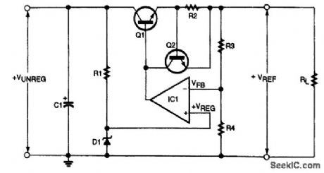
A current-limiting transistor and resistor protect the pass transistor and rectifier bridge in this linear supply. (View)
View full Circuit Diagram | Comments | Reading(840)
PULSE_FREQUENCY_MODULATED_RECEIVER
Published:2009/7/17 2:31:00 Author:Jessie
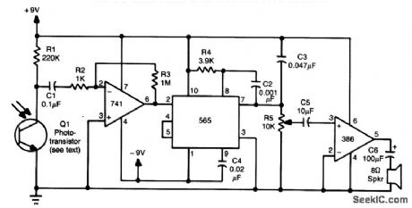
This receiver uses an IR-sensitive phototransistor (Clairex, HP, etc.) mounted in a light-tight enclosure with an aperture for the incoming IR beam. An optical system can be used with this receiver for increased range. A 741 amplifies the pulsed IR signal and a 565 PLL FM demodulator recovers the audio, which drives an LM386 audio amplifier and speaker. (View)
View full Circuit Diagram | Comments | Reading(1638)
| Pages:94/291 At 2081828384858687888990919293949596979899100Under 20 |
Circuit Categories
power supply circuit
Amplifier Circuit
Basic Circuit
LED and Light Circuit
Sensor Circuit
Signal Processing
Electrical Equipment Circuit
Control Circuit
Remote Control Circuit
A/D-D/A Converter Circuit
Audio Circuit
Measuring and Test Circuit
Communication Circuit
Computer-Related Circuit
555 Circuit
Automotive Circuit
Repairing Circuit