power supply circuit
FREQUENCY_PROBE
Published:2009/7/17 1:47:00 Author:Jessie | From:SeekIC

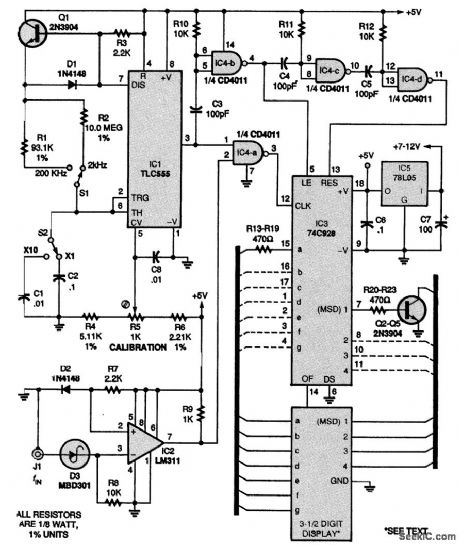
This design is a simplified 3 1/2-digit frequency counter with four ranges: 2000 Hz, 20.00 kHz, 200.0 kHz, and 2.000 MHz. An effort was made to miniaturize the circuit so that it would fit in a standard logic-probe-type case; the complete circuit was assembled on a perforated board cut down to 1×4 3/4 inches. The normal crystal time base with all its dividers was eliminated in favor of one eight-pin DIP: IC1, a TLC555 CMOS oscillator. It provides gate timings of 1000 ms, 100 ms, 10 ms, and 1 ms using R1, R2, C1, and C2 as the crucial timing components, Select C1 to be exactly 1/10 the value of C2. Calibration is done with trimmer potentiometer R5. Integrated circuit IC2 (an LM311) provides input conditioning for any waveform of ±0.9 to ±30 V, whether triangle, sine, or square wave. Integrated circuit IC4 (a CD4011 or 74C00) provides proper pulse delays to IC3, a 74C928 3 1/2-digit counter chip that directly drives a miniature 3 1/2- or 4-digit, common-cathode LED display. The digit drivers shown, Q2 to Q5 and R20 to R23, can be replaced with a single DIP package (such as a 7549, 75492, etc.). A 78 regulator, IC5, provides the +5 V for the circuit, and is mounted on the board with the other components. It can be driven externally via a standard ac wall adapter of 7 to 12 V at 30 mA, or from a 9-V battery. Be sure to bypass the supply pins on each IC with a 0.1-μF monolithic capacitor for noise-free performance. When accuracy is important, a crystal-controlled time base should be used.
Reprinted Url Of This Article:
http://www.seekic.com/circuit_diagram/Power_Supply_Circuit/FREQUENCY_PROBE.html
Print this Page | Comments | Reading(3)

Article Categories
power supply circuit
Amplifier Circuit
Basic Circuit
LED and Light Circuit
Sensor Circuit
Signal Processing
Electrical Equipment Circuit
Control Circuit
Remote Control Circuit
A/D-D/A Converter Circuit
Audio Circuit
Measuring and Test Circuit
Communication Circuit
Computer-Related Circuit
555 Circuit
Automotive Circuit
Repairing Circuit
Code: