
Index 314
Clock_tunable_notch_filter
Published:2009/7/24 13:17:00 Author:Jessie

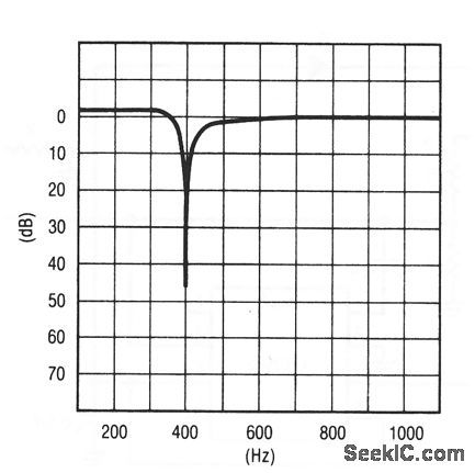
This circuit shows an LTC1062 and an op amp (such as an LT1056) connected to form a notch filter. Figure 7-22B shows the frequency response for a 400-Hz notch filter that uses the following values and equations: R3=R4=R5=10 kΩ, R1/R2=1.234Ω, fCLK/fnotch=79.3/1. Linear Technology Corporation, Linear Applications Handbook, 1990, p. AN24-6. (View)
View full Circuit Diagram | Comments | Reading(641)
_MULTIPLE_FEEDBACK__BANDPASS_FILTER(10_kHz)
Published:2009/6/30 2:32:00 Author:May

View full Circuit Diagram | Comments | Reading(621)
Selective_clock_sweepable_bandpass_filter
Published:2009/7/24 13:15:00 Author:Jessie
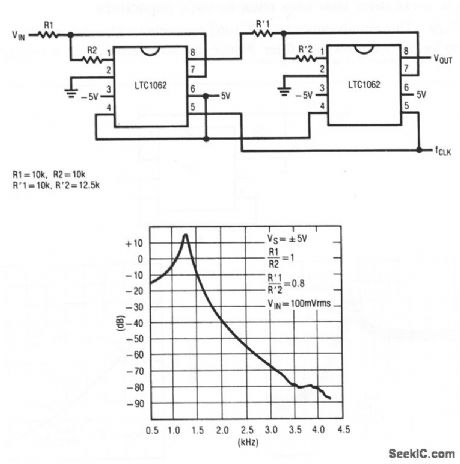
This circuit shows two LTC1062s connected to form a clock-sweepable bandpass filter. Figure 7-21B shows the frequency response for the values given in Fig. 7-21 A. Linear Technology Corporation, Linear Applications Handbook, 1990, p. AN24-5. (View)
View full Circuit Diagram | Comments | Reading(515)
Clock_sweepable_pseudo_bandpass_notch_filter
Published:2009/7/24 13:14:00 Author:Jessie
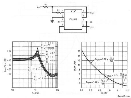
This circuit shows an LTC1062 connected as a simple clock-sweepable bandpass/notch filter. Figure 7-20B shows the frequency response for a clock frequency of 100 kHz and the various ratios of R1/R2. Figure 7-20C shows the variation of peak gain (Hop) and peak frequency (fp) versus different values of the R1/R2 ratio. Linear Technology Corporation, Linear Applications Handbook, 1990, p. AN24-4,-5. (View)
View full Circuit Diagram | Comments | Reading(479)
Simple_5_Hz_filter_that_uses_back_to_back_capacitors
Published:2009/7/24 13:13:00 Author:Jessie
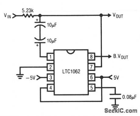
This circuit shows an LTC1062 connected with solid-tantalum capacitors to form a 5-Hz low-pass filter. Notice that no external clock is required. Linear Technology Corporation, Linear Applications Handbook, 1990, p. AN20-11. (View)
View full Circuit Diagram | Comments | Reading(707)
Extended_notch_filter
Published:2009/7/24 13:12:00 Author:Jessie

This circuit is similar to that of Fig. 7-17, but uses two sections of an LT1013 following the LTC1062. Figure 7-18B shows the frequency response for a 60-Hz notch filter that uses the values and equations of Fig. 7-18A. Linear Technology Corporation, Linear Applications Handbook, 1990, p. AN20-10,-11. (View)
View full Circuit Diagram | Comments | Reading(445)
IC_notch_filter
Published:2009/7/24 13:10:00 Author:Jessie
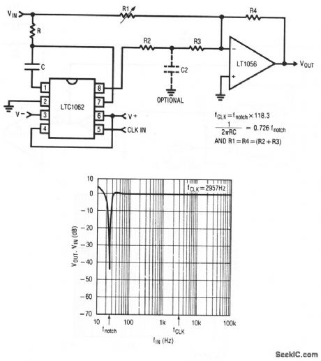
This circuit shows an LTC1062 and an LT1056 connected to form a notch filter. Figure 7-17B shows the frequency response for a 25-Hz notch filter using values based on the equations of Fig. 7-17A. The optional R2/C2 at the LTC1062 output is used to minimize clock feedthrough. The 1/(6.28R2C2) value should be 12 to 15 times that of the notch frequency. Linear Technology Corporation, Linear Applications Handbook, 1990, p. AN20-9, -10. (View)
View full Circuit Diagram | Comments | Reading(904)
DC_MULTIPLIERS
Published:2009/6/30 2:25:00 Author:May
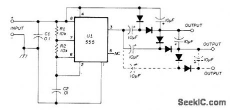
Voltage output from positive voltage booster (+12 VDC to +20 VDC) is increased by using diode-capacitor voltage-doubler sections as shown. Diodes are 1N914, 1N4148, or equivalent. Doubling is achieved at expense of available current. Same technique may be used to increase output of DC/DC converter having negative output voltage.—G. A. Graham, Low-Power DC-DC Converter, Ham Radio, March 1975, p 54-56. (View)
View full Circuit Diagram | Comments | Reading(3816)
Basic_tuned_circuit
Published:2009/7/24 13:40:00 Author:Jessie

This circuit uses an LM101A to form a single-stage tuned circuit. The output frequency is determined by the values of R1, R2, C1, and C2, as shown by the equation. National Semiconductor, Linear Applications Handbook, 1991, p. 95. (View)
View full Circuit Diagram | Comments | Reading(534)
Two_stage_tuned_circuit
Published:2009/7/24 13:39:00 Author:Jessie

This circuit uses two LM102s to fonn a two-stage tuned circuit. National Semiconductor, Linear Applications Handbook, 1991, p. 95. (View)
View full Circuit Diagram | Comments | Reading(439)
Easily_tuned_notch_filter
Published:2009/7/24 13:39:00 Author:Jessie
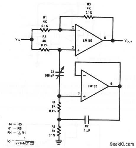
This circuit uses two LM107s to form a tunable notch filter. The notch frequency is set by adjustment of C1. The frequency range is determined by the values of R4,C1, and C2, as shown by the equation. National Semiconductor, Linear Applications Handbook, 1991, p. 95. (View)
View full Circuit Diagram | Comments | Reading(1024)
Adjustable_Q_notch_filter
Published:2009/7/24 13:37:00 Author:Jessie

This circuit uses two LM100s to form a 60-Hz notch filter with adjustable Q(set by adjustment of R4). Other frequencies can be selected using the equation. National Semiconductor, Linear Applications Handbook, 1991, p. 94. (View)
View full Circuit Diagram | Comments | Reading(3677)
Bi_quad_RC_active_bandpass_filter
Published:2009/7/24 13:36:00 Author:Jessie

This circuit uses three LM3900 Norton amplifiers as a 1-kHz bandpass filter with a Q of 50, and a gain of 100 (40 dB). National Semiconductor, Linear Applications Handbook, 1991, p. 230. (View)
View full Circuit Diagram | Comments | Reading(764)
Two_op_amp_bandpass_filter
Published:2009/7/24 13:36:00 Author:Jessie
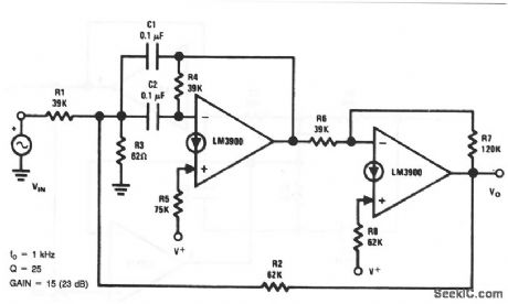
This circuit uses two LM3900 Norton amplifiers as a 1-kHz bandpass filter with a Q of 25, and a gain of 15 (23 dB). National Semiconductor, Linear Applications Handbook, 1991, p. 229. (View)
View full Circuit Diagram | Comments | Reading(1453)
One_op_amp_bandpass_filter
Published:2009/7/24 13:35:00 Author:Jessie
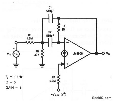
This circuit uses an LM3900 Norton amplifier as a 1-kHz bandpass filter with a Q of 5 and unity gain. National Semiconductor, Linear Applications Handbook, 1991, p. 228. (View)
View full Circuit Diagram | Comments | Reading(2120)
100_kHz_high_pass_2_pole_Butterworth_filter
Published:2009/7/24 13:32:00 Author:Jessie

This circuit uses an HA-2544 video op amp (Fig. 3-29) to form an active 100-kHz filter. Other frequencies can be selected using the equation. Figure 7-26B shows the filter characteristics. Harris Semiconductor, Linear & Telecom ICs, 1991, p. 3-312. (View)
View full Circuit Diagram | Comments | Reading(505)
IC_filter_with_programmed_cutoff_frequencies
Published:2009/7/24 13:31:00 Author:Jessie
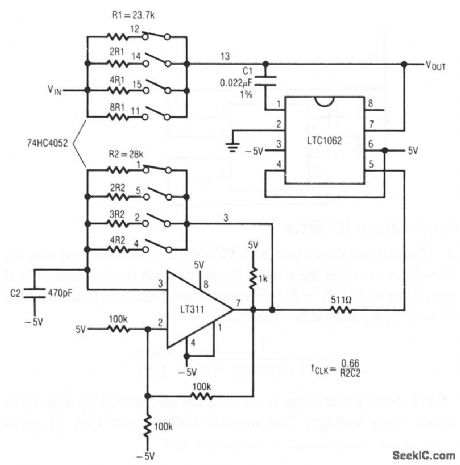
This circuit shows an LTC1062 used with a dual four-channel MUX (74HC4052) and an LT311 to provide four different cutoff frequencies (500, 250, 125, and 62.5 Hz). Notice that the clock frequency and the external R×C product are varied simultaneously so that: 1/(6.28RC) =fc/1.64=fclock/1.64. Linear Technology Corporation, Linear Applications Handbook, 1992, p. AN24-8. (View)
View full Circuit Diagram | Comments | Reading(711)
IC_filter_operated(from_±15_V)supplies
Published:2009/7/24 13:29:00 Author:Jessie

This circuit shows an LTC1062 interfaced with an LT1013 op amp and operated from ±15-V supplies.The desired cutoff frequency is determined by the equation shown. A typical dc output is 300 mV. Linear Technology Corporation, Linear Applications Handbook, 1992, p. AN24-7. (View)
View full Circuit Diagram | Comments | Reading(402)
Full_duplex_300_baud_modem_filter
Published:2009/7/24 14:03:00 Author:Jessie
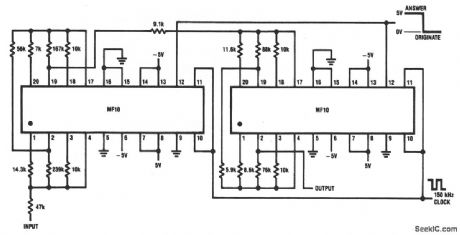
This circuit is an 8th-order 1-dB ripple Chebyshev bandpass, which functions as both an 1170-Hz originate filter, and a 2125-Hz answer filter. Only one clock is required, and overall gain is 22 dB. National Semiconductor, Linear Applications Handbook, 1991, p. 912. (View)
View full Circuit Diagram | Comments | Reading(587)
4th_order_1_kHz_Butterworth_switched_filter
Published:2009/7/24 14:02:00 Author:Jessie
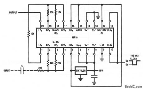
Only six resistors are required for this low-pass filter. However, a 100-kHz clock is required. National Semiconductor, Linear Applications Handbook, 1991, p. 910. (View)
View full Circuit Diagram | Comments | Reading(505)
| Pages:314/471 At 20301302303304305306307308309310311312313314315316317318319320Under 20 |
Circuit Categories
power supply circuit
Amplifier Circuit
Basic Circuit
LED and Light Circuit
Sensor Circuit
Signal Processing
Electrical Equipment Circuit
Control Circuit
Remote Control Circuit
A/D-D/A Converter Circuit
Audio Circuit
Measuring and Test Circuit
Communication Circuit
Computer-Related Circuit
555 Circuit
Automotive Circuit
Repairing Circuit