Basic Circuit
Selective_clock_sweepable_bandpass_filter
Published:2009/7/24 13:15:00 Author:Jessie | From:SeekIC
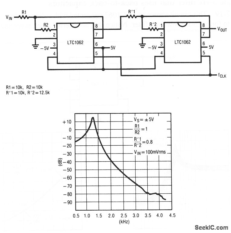
This circuit shows two LTC1062s connected to form a clock-sweepable bandpass filter. Figure 7-21B shows the frequency response for the values given in Fig. 7-21 A. Linear Technology Corporation, Linear Applications Handbook, 1990, p. AN24-5.
Reprinted Url Of This Article:
http://www.seekic.com/circuit_diagram/Basic_Circuit/Selective_clock_sweepable_bandpass_filter.html
Print this Page | Comments | Reading(3)

Article Categories
power supply circuit
Amplifier Circuit
Basic Circuit
LED and Light Circuit
Sensor Circuit
Signal Processing
Electrical Equipment Circuit
Control Circuit
Remote Control Circuit
A/D-D/A Converter Circuit
Audio Circuit
Measuring and Test Circuit
Communication Circuit
Computer-Related Circuit
555 Circuit
Automotive Circuit
Repairing Circuit
Code: