
Audio Circuit
Index 31
ONE_TRANSISTOR_AUDIO_MIXER
Published:2009/6/24 2:20:00 Author:May

Three or more inputs with individual level controls feed into the base of Q1 that provides a voltage gain of 20. (View)
View full Circuit Diagram | Comments | Reading(1644)
ELECTRONIC_METRONOME
Published:2009/6/23 22:56:00 Author:Jessie

RA sets the rate while R, sets the volume of clocks in the speaker. The 555 is configured as a low frequency oscillator. The circuit is powered 2N3904 by a 6 V battery. (View)
View full Circuit Diagram | Comments | Reading(1262)
MUSICAL_INSTRUMENT_DIGITAL_INTERFACEMIDIRECEIVER
Published:2009/6/23 22:54:00 Author:Jessie

Receiver photodiode SFH250 is used to convert optical data pulses at 32.5 Kb to electrical signals. Buffer T2 feeds the signals to cascade amplifier T3-T4, then to op amp IC4, and buffers IC5-f and IC5-e. IC6 supplies 9 V for the circuit. (View)
View full Circuit Diagram | Comments | Reading(2571)
PERFECT_PITCH
Published:2009/6/23 22:50:00 Author:Jessie

Perfect pitch, which is based on the 8751 H microprocessor, is an inexpensive and easy-to-build instrument tuner/frequency counter with a built-in headphone amplifier and a visual metronome. Perfect pitch converts the audio signal from your instrument to a digital signal, and displays the musical note you are playing and its frequency in real time on a 16-character liquid-crystal display. It also has an auxiliary audio input for radio, tape, or CD players so that you can tune up and play along with your favorite artists. (View)
View full Circuit Diagram | Comments | Reading(2267)
PRECISION_AUDIO_GENERATOR_FOR_MUSICAL_INSTRUMENT_TUNE_UP
Published:2009/6/23 22:44:00 Author:Jessie

One section of the precision audio frequency generator use an electret microphone element to pick up audio from the piano. That signal is then processed and sent to one channel of a dual-trace oscilloscope. The other section of the circuit is used to produce a variabe-frequency that is fed to a digital frequency counter. After conditioning, the audio signal is presented to the second channel of the scope and output to a set of stereo headphones. (View)
View full Circuit Diagram | Comments | Reading(1528)
WARBLE_OSCILLATOR
Published:2009/6/23 4:41:00 Author:Jessie

Sections A & B form an oscillator running at 2 Hz, which gates sections C and D, a 1-kHz oscilla-tor. This drives the TIP31 speaker driver. (View)
View full Circuit Diagram | Comments | Reading(1403)
DUAL_TONE_GENERATOR_FOR_AUDIO_SERVICING
Published:2009/6/23 3:34:00 Author:Jessie

This dual-tone generator can insert a distinctive tone in the audio section of a circuit under test.That way, you can work your way back from the speaker, stage-by-stage, to locate a faulty section. (View)
View full Circuit Diagram | Comments | Reading(0)
UNDERWATER_MICROPHONE
Published:2009/6/23 2:17:00 Author:May
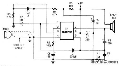
This circuit uses a TBA820 audio IC to amplify underwater sounds. The microphone must be waterproofed. This project was originally used in a home aquarium to monitor fish sounds. (View)
View full Circuit Diagram | Comments | Reading(2466)
SIMPLE_EXTERNAL_MICROPHONE_CIRCUIT_FOR_TRANSCEIVERS
Published:2009/6/23 2:11:00 Author:May

Used originally for an Icom ICZAT handie talkie, this circuit might prove useful in other applications. (View)
View full Circuit Diagram | Comments | Reading(907)
TWO_METER_PREAMPLIFIER_FOR_HANDITALKIES
Published:2009/6/23 1:37:00 Author:May

This simple, inexpensive, wideband rf amplifier provides 14 dB gain on two meters without the use of tuned circuits. (View)
View full Circuit Diagram | Comments | Reading(869)
DITHERIZER
Published:2009/6/22 23:54:00 Author:Jessie

In digital audio, a noise signal of amplitude less than one significant bit is often added to the au-dio to reduce the quantizing effect and improve the audio quality by trading digital noise for ana-log noise, which does not have the harsh sound. This circuit consists of a noise generator to add a low level of noise to an analog signal to be digitized, or an analog signal from a digital source. (View)
View full Circuit Diagram | Comments | Reading(1534)
TTL_BASED_AUDIO_OSCILLATOR
Published:2009/6/22 23:49:00 Author:Jessie

Half a 7404 will produce a tone around 1000 Hz with this circuit. (View)
View full Circuit Diagram | Comments | Reading(3653)
AUDIO_VOLUME_LIMITER
Published:2009/6/22 23:49:00 Author:Jessie

In this circuit,amplifier IC1-a provides signal amplification of 40 to+40 dB depending on thevalue of the LDR The LDR(ight dependent resistor)is driven by rectified audio from voltage follower IC1b and bridge rectifier D1 through D4 (View)
View full Circuit Diagram | Comments | Reading(0)
LOW_FREQUENCY_ASTABLE
Published:2009/6/22 23:49:00 Author:Jessie


By using a high-gain low-current transistor, such as the 2N3565, a pair of Darlington-connected transistors (2N3565 and 2N3904) can be used in a high-impedance configuration. (View)
View full Circuit Diagram | Comments | Reading(1327)
QUAD_TONE_OSCILLATOR
Published:2009/6/22 23:40:00 Author:Jessie

A quad op amp (TL084, etc.) can be used to produce four audio tone generators for use in a test setup. The circuit uses a 12-V supply. (View)
View full Circuit Diagram | Comments | Reading(3053)
EASILY_TUNED_SINE_WAVE_OSCILLATOR
Published:2009/6/22 23:39:00 Author:Jessie

The circuit will provide both a sine-and square-wave output for frequencies from below 20 Hz to above 20 kHz. The frequency of oscillation is easily tuned by varying a single resistor. This is a considerable advantage over Wien bridge circuits, where two elements must be tuned simultaneously to change frequency. Also, the output amplitude is relatively stable when the frequency is changed.An operational amplifier is used as a tuned circuit, driven by square wave from a voltage comparator. Frequency is controlled by R1, R2, C1, C2, and R3, with R3 used for tuning. Tuning the filter does not affect its gain or bandwidth, so the output amplitude does not change with frequency. A comparator is fed with the sine-wave output to obtain a square wave. The square wave is then fed back to the input of the tuned circuit to cause oscillation. Zener diode, D1, stabilizes the amplitude of the square wave fed back to the filter input. Starting is ensured by R6 and C5, which provide dc negative feedback around the comparator. This keeps the comparator in the active region (View)
View full Circuit Diagram | Comments | Reading(2033)
AUDIBLE_CONTINUITY_TESTER
Published:2009/6/22 23:35:00 Author:Jessie

View full Circuit Diagram | Comments | Reading(1517)
COMBINATION_SYNC_STRIPPER_AND_UNIVERSAL_VIDEO_INTERFACE
Published:2009/6/19 4:59:00 Author:May

This combination sync stripper and universal video interface can solve a lot of problems for you, including Super-Nintendo-to-anything interfacing, video overlay and scope TV frame locking. Kits, fully tested units, and custom cable assemblies are available through Redmond Cable. This unit uses an LM1881 (NS) synch separator IC. (View)
View full Circuit Diagram | Comments | Reading(4282)
AUDIO_LIMITER
Published:2009/6/19 4:59:00 Author:May

An optoisolator is used as an attenuator in this circuit. When the LM386 draws more current on audio signals, the 2N3638 turns on, which biases the optoisolator on, and reduces the volume. (View)
View full Circuit Diagram | Comments | Reading(1995)
RADIO_COMMERCIAL_ZAPPER
Published:2009/6/19 4:55:00 Author:May

The L&R inputs are summed, dated and drive a comparator. The comparator senses level and generates a transition when audio inputs go above or below preset thresholds. The number of these transitions (corresponding to rapid volume changes) are integrated and feed voltage controlled amplifiers. This device actually senses dynamic range. (View)
View full Circuit Diagram | Comments | Reading(930)
| Pages:31/54 At 202122232425262728293031323334353637383940Under 20 |
Circuit Categories
power supply circuit
Amplifier Circuit
Basic Circuit
LED and Light Circuit
Sensor Circuit
Signal Processing
Electrical Equipment Circuit
Control Circuit
Remote Control Circuit
A/D-D/A Converter Circuit
Audio Circuit
Measuring and Test Circuit
Communication Circuit
Computer-Related Circuit
555 Circuit
Automotive Circuit
Repairing Circuit