
Audio Circuit
Index 38
Multiple Music Doorbell Circuit
Published:2011/7/8 1:09:00 Author:Joyce | Keyword: Multiple Music , Doorbell

The music doorbell as shown in the figure is composed of several musical circuit. When the visitors press the doorbell , they can hear constantly changing music , which will, on one hand, alleviate the visitors` anxiety; on the other hand, provide the host with enough time to open the door while stops his/her current work. As shown in the figure, the circuit is composed of a doorbell triggering circuit, multiple music automatically switch circuit and several musicals. (View)
View full Circuit Diagram | Comments | Reading(1251)
Touch Diphonia Doorbell Circuit
Published:2011/7/8 8:37:00 Author:Joyce | Keyword: Touch, Diphonia , Doorbell

As shown in the figure, the touch daphnia doorbell does not have a button, but has a pair of touch slices as the starting switch. When one’s hand touches the slice, a certain amount of high level gained by the slice from the power source through the human resistance will start the circuit, which is as shown in the figure. The circuit is composed by a CD4069 of six inverters. Two of the gates constitute start-and-stop circuit, two gates form an audio oscillator, and the rest two doors compose a rhythm oscillator of the audio oscillator (View)
View full Circuit Diagram | Comments | Reading(725)
Visitor Identified Doorbell Circuit
Published:2011/7/8 1:07:00 Author:Joyce | Keyword: Visitor Jdentified , Doorbell

Here, a visitor could be a family member, an acquaintance or a stranger. The reason why the doorbell can differentiate the identity of visitors is not only due to the special design of the circuit structure, but also taking advantage of the psychology and the common habits of people. The doorbell can be divided into three groups: single button, two buttons and three buttons. To strangers who don’t know the inside well, he won't press two or three buttons at the same time, but he will press one of buttons, which will not trigger the doorbell. (View)
View full Circuit Diagram | Comments | Reading(875)
Power Amplifier Circuit Made of LM317
Published:2011/7/8 0:40:00 Author:Joyce | Keyword: Power Amplifier

This circuit is Pure Class A, and using a low noise tube as its voltage amplifier, so the THD, NF indexs are quite good. Its output power can reach 30 W. As shown in the figure, VT1 transistor is used as voltage amplifier, because the input impedance of the integrated circuit IC1 is high, the working current of 0.6 mA is enough. R1, C3 are power decouplings, and C4 is used to prevent parasitic oscillation. R3, R4 will divide pressure to provide offset and ac/dc feedback to VT1 to improve the linearity and dc stability. VT2, R5, R6 and diode form a constant flow source, which is used to improve the efficiency and output power of the circuit, and increase the output dynamic range. (View)
View full Circuit Diagram | Comments | Reading(4762)
Sirens Generator Circuit Composed of Gate Circuit
Published:2011/7/8 8:36:00 Author:Joyce | Keyword: Sirens Generator, Gate Circuit

A multivibrator with sirens composed of gate circuit can drive LEDs to generate a great amount of changing colors. Pulse output through multivibrator can drive the speaker to produce sound. Signals with one frequency can make the speaker produce sound with single frequency; Signals with several frequencies can make it produce different sounds. According to this principle, one can have a mix of signal sources with different frequency to obtain the various sounds needed. As shown in the figure l is the siren generator composed of gate circuit. (View)
View full Circuit Diagram | Comments | Reading(1045)
Twitter Generator Circuit Composed of CD4046
Published:2011/7/8 1:04:00 Author:Joyce | Keyword: Twitter, Generator
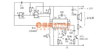
As shown in the figure is the twitter generator circuit composed of CD4046 (View)
View full Circuit Diagram | Comments | Reading(3127)
Phase Shift Alarm Generator Circuit Composed of CD4046
Published:2011/7/8 1:03:00 Author:Joyce | Keyword: Phase Shift , Alarm , Generator

As shown in the circuit is the phase shift alarm generator circuit composed of CD4046 (View)
View full Circuit Diagram | Comments | Reading(1792)
Alarm Generator Circuit Composed of CD4046
Published:2011/7/8 1:03:00 Author:Joyce | Keyword: Alarm , Generator

The voltage-controlled oscillator installed within CD4046 has very good practicability. Though its internal circuit structure is very complex, the usage is quite simple. While using CD4046, through regulating the control voltage of its foot ⑨, one can make the oscillation frequency of the vco varies in a wide range. And controlling its feet⑤ can make it start or stop oscillation easily. This structure of the circuit gives it a unique advantage in all kinds of alarm circuit. As shown in the figure is the alarm generator composed of CD4046. (View)
View full Circuit Diagram | Comments | Reading(4573)
The Children lost warning devices NE555 and TDA7000
Published:2011/6/14 2:50:00 Author:TaoXi | Keyword: Children lost, warning device
The FM transmitter circuit has two parts: the low frequency modulation oscillator and the carrier frequency oscillator transmitter circuit, as the figure (a) shown.
The receiving circuit is as shown in figure (b).
(View)
View full Circuit Diagram | Comments | Reading(633)
Circuit of Telephone with Increasing Volume
Published:2011/7/8 0:40:00 Author:Joyce | Keyword: Telephone , Increasing Volume
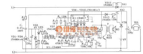
The circuit of telephone with increasing volume is an auxiliary device attached to the telephone externally, which would produce the needed bell signal, while the bell ring sent by telephone lines works only as the control signal of the circuit . In this circuit, the bell signal is generated by the multivibrator composed of gate circuit CD4069, and the amplification and output of the volume of oscillator is controlled by a field effect transistor through its transconductance of the change of Gm. And the change of the Gm is realized by the times of bell ring sent by telephone lines going through CD4017`s shift function. The composition of the circuit is as shown. (View)
View full Circuit Diagram | Comments | Reading(769)
50W Thick Film Power Amplifier Circuit Composed of STK084G
Published:2011/7/8 0:38:00 Author:Joyce | Keyword: 50W, Thick Film, Power Amplifier

Figure (a) is a 50 W output power amplifier circuit composed of STK084G thick film power amplifier. STK084G is a thick-film integrated chip whose distortion rate is 0.01% in 20 kHz, 50 W. Its internal equivalent circuit is as shown in figure (b) .The input stage is a current mirror circuit composed of VT4 and VT5, which will transform the differential motion output to single-ended output to get a larger gain. VT8 uses ground connection to reduce the influence of Miller effect on its high frequency characteristics. VT1 and VT6 are constant current offset circuits,and they can restrain the influence of power change on the circuit. VT7 is used to output transistor offset. (View)
View full Circuit Diagram | Comments | Reading(1857)
LA3361 audio IC circuit
Published:2011/7/10 19:04:00 Author:TaoXi | Keyword: audio IC

The LA3361 audio IC circuit is as shown in the figure:
(View)
View full Circuit Diagram | Comments | Reading(3971)
LA3225T-6T audio IC circuit
Published:2011/7/10 19:03:00 Author:TaoXi | Keyword: audio IC

The LA3225T-6T audio IC circuit is as shown in the figure:
(View)
View full Circuit Diagram | Comments | Reading(1583)
LA4145 audio IC circuit
Published:2011/7/10 19:20:00 Author:TaoXi | Keyword: audio IC

The LA4145 audio IC circuit is as shown in the figure:
(View)
View full Circuit Diagram | Comments | Reading(1010)
LA4101 audio IC circuit
Published:2011/7/10 19:11:00 Author:TaoXi | Keyword: audio IC

The LA4101 audio IC circuit is as shown in the figure:
(View)
View full Circuit Diagram | Comments | Reading(1612)
LA3600 audio IC circuit
Published:2011/7/10 19:09:00 Author:TaoXi | Keyword: audio IC

The LA3600 audio IC circuit is as shown in the figure:
(View)
View full Circuit Diagram | Comments | Reading(4404)
VT66/66A Transistor Music Integrated Circuit
Published:2011/7/8 4:25:00 Author:Joyce | Keyword: VT66/66A, Transistor, Music, Integrated


VT66/66 A is packed in TO92 form, and its appearance looks like 9013 transistor. What’s more, it has a piece of metal cooling fin and 3 leading feet.Since it is as convenient as general transistor, some give it the name music transistor. As shown in the figure is its typical application circuit.
The relationship between the names of music stored in VT66/66 and chip numbers
src= /uploadfile/ic-circuit/20117842515914.gif border=0> (View)
View full Circuit Diagram | Comments | Reading(2273)
Light Control Music Integrated Circuit
Published:2011/7/8 4:39:00 Author:Joyce | Keyword: Light Control, Music , Integrated

KD-1548 is a large-scale integrated circuit. It can realize the function of light control through connecting photo-resistor (CDS) externally; it can also work as an ordinary music integrated circuit. So it is widely used in electric reminders, alarm devices, electric toys, crafts, etc.The typical application circuit of KD 1548 as light control trigger is as shown in the figure(a) ; While figure(b) shows the situation when it is used as a common music integrated circuit. At this moment, if pressing the button OSH only, the circuit will be triggered and it will automatically stop when a song is finished. If pressing LH, the music will start, but it will stop once you loosen LH. (View)
View full Circuit Diagram | Comments | Reading(1034)
Password Electronic Doorbell Circuit
Published:2011/7/8 1:43:00 Author:Joyce | Keyword: Password, Electronic , Doorbell

The password electronic doorbell is actually one that can tell whether it is a member of family and a visitor .Because a family member knows the password, when he presses the password, the doorbell will give out a kind of music. While a visitor does not know the password, so he presses a pseudo code and the doorbell will give out a specific sound, which enable the host to distinguish family members and visitors .The circuit is as shown in the figure. The circuit is composed by a four-two input Schmitt trigger CD4093 and two sound circuits, of which three doors of CD4093 D1 ~ D3 and buttons SA1 ~ SA3 forming a logic control circuit. (View)
View full Circuit Diagram | Comments | Reading(948)
Ring-simulated Doorbell Circuit
Published:2011/7/8 1:58:00 Author:Joyce | Keyword: Ring-simulated, Doorbell

As shown in the figure, the circuit uses a 14 bit binary serial count/frequency divider and an oscillator of CD4060 oscillator to produce oscillating impulse with certain frequency. The oscillating impulse will send out a doorbell simulating that of a ring after certain processing. The main circuit is composed by a 14 bit binary serial count/frequency divider and oscillator CD4060. (View)
View full Circuit Diagram | Comments | Reading(1177)
| Pages:38/54 At 202122232425262728293031323334353637383940Under 20 |
Circuit Categories
power supply circuit
Amplifier Circuit
Basic Circuit
LED and Light Circuit
Sensor Circuit
Signal Processing
Electrical Equipment Circuit
Control Circuit
Remote Control Circuit
A/D-D/A Converter Circuit
Audio Circuit
Measuring and Test Circuit
Communication Circuit
Computer-Related Circuit
555 Circuit
Automotive Circuit
Repairing Circuit