
Audio Circuit
Index 20
80_watt_175_MHz_FM_transmitter_for_125_volt_operation
Published:2009/7/20 7:29:00 Author:Jessie
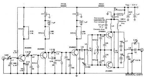

80-watt 175 MHz FM transmitter for 12.5-volt operation. Forthe rated output of 80 watts 180 mW of RF drive is required (courtesy MotorolaJ Semiconductor Products Inc.). (View)
View full Circuit Diagram | Comments | Reading(2391)
Single_stage_80_watt_RF_power_amplifier_for_144_to_175_MHz_FM_operation
Published:2009/7/20 7:26:00 Author:Jessie

Single-stage 80-watt RF power amplifier for 144 to 175 MHz FM operation. About 25 watts of drive are required for the rated output (courtesy Motorola Semiconductor Products mc.). (View)
View full Circuit Diagram | Comments | Reading(1806)
13_vatt_microstrip_UHF_amplifier_for_220_to_225_MHz
Published:2009/7/20 7:22:00 Author:Jessie

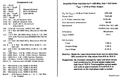
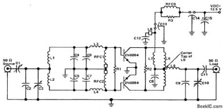
13-vatt microstrip UHF amplifier for 220 to 225 MHz (ouurtesy Motorola Semiconductor Products Inc.). (View)
View full Circuit Diagram | Comments | Reading(934)
160_watt_PEP_broadband_linear_amplifier_for_28_volt_operation_
Published:2009/7/20 7:20:00 Author:Jessie
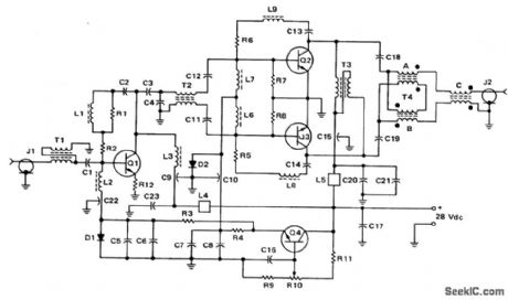
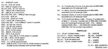
160-watt PEP broadband linear amplifier for 28-volt operation (courtesy Motorola Semiconductor Products Inc.). (View)
View full Circuit Diagram | Comments | Reading(893)
Two_stage_80_watt_RF_poweramplifier_for_144_to_175_MHz_FM_operation
Published:2009/7/20 7:18:00 Author:Jessie

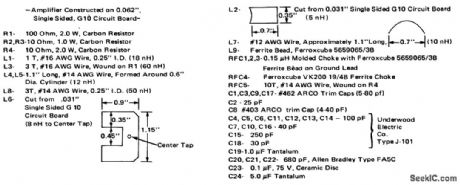
Two-stage 80-watt RF poweramplifier for 144 to 175 MHz FM operation. About 5.5 watts ofdrive are required torthe rated output (courtesy Motorola Semiconductor Products Inc.). (View)
View full Circuit Diagram | Comments | Reading(1062)
80_watt_PEP_broadband_linear_amplifier_for_125_volt_operation
Published:2009/7/20 7:15:00 Author:Jessie


80-watt PEP broadband linear amplifier for 12.5-volt operation (courtesy Motorola Semiconductor Products Inc.) (View)
View full Circuit Diagram | Comments | Reading(877)
Balanced_modulator_circuit_using_an_MC1596G
Published:2009/7/20 7:13:00 Author:Jessie

Balanced modulator circuit using an MC1596G. For a maximum modulating signal input of 300 mV RMS, the suppression of spurious sideband is typically 55 dB at a carrier frequency of 500 kHz (courtesy Motorola Semiconductor Products Inc.). (View)
View full Circuit Diagram | Comments | Reading(2202)
30_MHz_RF_amplifier_with_limiting_using_the_EGC703A_10
Published:2009/7/20 7:12:00 Author:Jessie

30 MHz RF amplifier with limiting using the EGC703A 10 (courtesy of GTE Sylvania Incorporated). (View)
View full Circuit Diagram | Comments | Reading(907)
100_MHz_RF_amplifier_using_the_ECG703A_IC
Published:2009/7/20 7:12:00 Author:Jessie
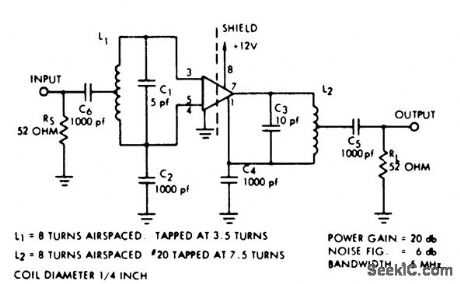
100 MHz RF amplifier using the ECG703A IC. Reverse AGO may be obtained at pin 5 (courtesy GTE Sylvania incorporated). (View)
View full Circuit Diagram | Comments | Reading(926)
107_MHz_to_45_MHz_convener_using_two_3N204_dual_gate_MOSFETs
Published:2009/7/20 7:08:00 Author:Jessie

10.7 MHz to 45 MHz convener using two 3N204 dual-gate MOSFETs(courtesy Texas Instruments Incorporated). (View)
View full Circuit Diagram | Comments | Reading(766)
Double_balanced_mixer_with_broadband_inputs_and_9_MHz_tuned_output
Published:2009/7/20 7:07:00 Author:Jessie
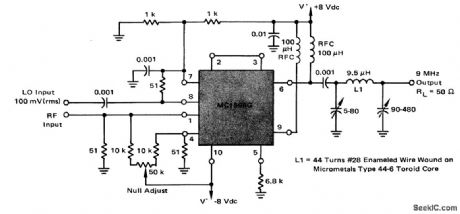
Double balanced mixer with broadband inputs and 9 MHz tuned output. The 3 dB bandwidth of the 9 MHz output tank is 450 kHz. Since the input is broadband the circuit can operate from HF to VHF. The local oscillator frequency should be +9 MHz (courtesy Motorola Semiconductor Products Inc.). (View)
View full Circuit Diagram | Comments | Reading(960)
25_watt_UHF_amplifier_for_450_to_512_MHz
Published:2009/7/20 7:05:00 Author:Jessie
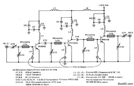
25-watt UHF amplifier for 450 to 512 MHz (courtesy Motorola Semiconductor Products Inc.). (View)
View full Circuit Diagram | Comments | Reading(992)
Product_detector_using_an_MC1596G
Published:2009/7/20 7:03:00 Author:Jessie
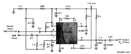
Product detector using an MC1596G. This circuit requires a single +12-volt supply. The circuit performs well with carrier level of 100 to 500 m VRMS. No transformers or tuned circuits are required for excellent performance from very low frequencies up to 100 MHz The audio output at pin 6 can be used to drive AGO (courtesy Motorola Semiconductor Products Inc.). (View)
View full Circuit Diagram | Comments | Reading(929)
Amplitude_modulator_using_an_MC1596G
Published:2009/7/20 7:00:00 Author:Jessie

Amplitude modulator using an MC1596G. Modulation levels from zero to greater than 100% can be obtained with this circuit (courtesy Motorola Semiconductor Products Inc.). (View)
View full Circuit Diagram | Comments | Reading(1668)
30_MHz_RF_to_5_MHz_IF_mixer
Published:2009/7/20 6:59:00 Author:Jessie

30 MHz RF to 5 MHz IF mixer. Injection point for the external local oscillator is at point A. The injection frequency is 35 MHz. The output of the 2N221A mixer is tuned to the difference of the two signals (courtesy Motorola Semiconductor Products Inc.). (View)
View full Circuit Diagram | Comments | Reading(988)
200_MHz_RF_amplifier_using_the_ECG703A_10_
Published:2009/7/20 6:58:00 Author:Jessie
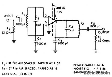
200 MHz RF amplifier using the ECG703A 10 (courtesy of GTE Sylvania Incorporated). (View)
View full Circuit Diagram | Comments | Reading(886)
30_MHz_PF_amplifier_with_transformer_coupling_using_the_EOG703A_
Published:2009/7/20 6:57:00 Author:Jessie
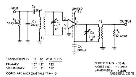
30 MHz PF amplifier with transformer coupling using the EOG703A (courtesy GTE Sylvania Incorporated). (View)
View full Circuit Diagram | Comments | Reading(909)
25_watt_AM_transmitter_designed_for_118_MHz_to_136_MHz_operation
Published:2009/7/20 6:55:00 Author:Jessie

2.5-watt AM transmitter designed for 118 MHz to 136 MHz operation (courtesy Motorola Semiconductor Products Inc.). (View)
View full Circuit Diagram | Comments | Reading(2069)
Two_stage_60_MHz_IF_amplifier_with_power_gain_of_80_dB_and_bandwidth_of_15MHz
Published:2009/7/20 6:53:00 Author:Jessie
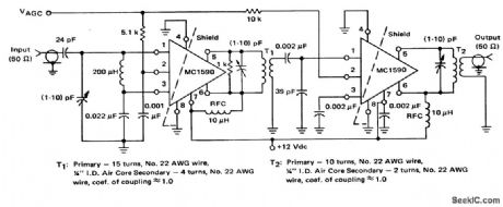
Two-stage 60 MHz IF amplifier with power gain of 80 dB and bandwidth of 1.5MHz (courtesy Motorola Semiconductor Products Inc.). (View)
View full Circuit Diagram | Comments | Reading(1103)
100_MHz_mixer_using_an_MC1590_BF_IF_amplifier
Published:2009/7/20 6:52:00 Author:Jessie

100 MHz mixer using an MC1590 BF-IF amplifier (courtesy Motorola Semiconductor Products Inc.). (View)
View full Circuit Diagram | Comments | Reading(1398)
| Pages:20/54 1234567891011121314151617181920Under 20 |
Circuit Categories
power supply circuit
Amplifier Circuit
Basic Circuit
LED and Light Circuit
Sensor Circuit
Signal Processing
Electrical Equipment Circuit
Control Circuit
Remote Control Circuit
A/D-D/A Converter Circuit
Audio Circuit
Measuring and Test Circuit
Communication Circuit
Computer-Related Circuit
555 Circuit
Automotive Circuit
Repairing Circuit