
Audio Circuit
Index 8
Simple Crystal Radio
Published:2012/10/22 22:03:00 Author:muriel | Keyword: Simple Crystal Radio
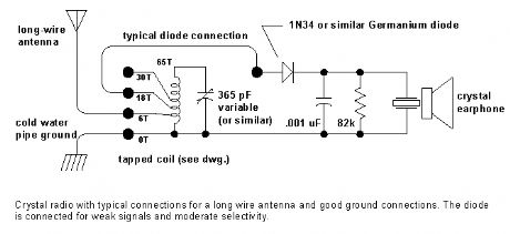
The crystal radio gets its name from the galena crystal (lead sulfide) used to rectify the signals. A cat's whisker wire contact was moved about the surface of the crystal until a diode junction was formed. The 1N34A germanium diode is the modern substitute for galena and most other germanium small-signal diodes will also work well. Silicon diodes are not a good choice because their much higher barrier potential requires larger signals for efficient rectification. Certain silicon Schottky diodes with low barrier potential will work well but most small-signal Schottky diodes will not perform as well as a garden-variety germanium diode. (View)
View full Circuit Diagram | Comments | Reading(0)
LED VU Meter
Published:2012/10/19 0:38:00 Author:muriel | Keyword: LED VU, Meter

The circuit below uses two quad voltage comparators (LM339) to illuminate a series of 8 LEDs indicating volume level. Each of the 8 comparators is biased at increasing voltages set by the voltage divider so that the lower right LED comes on first when the input is about 400 millivolts or about 22 milliwatts peak in an 8 ohm system. The divider voltages are set so that each LED represents about twice the power level as the one before so the scale extends from 22 milliwatts to about 2.5 watts when all LEDs are lit. The sensitivity can be decreased with the input control to read higher levels. I have not built or tested this circuit, so please let me know if you have problems getting it working. The power levels should be as follows:
1 LED = 22mW
2 LEDs = 42mW
3 LEDs = 90mW
4 LEDs = 175mW
5 LEDs = 320mW
6 LEDs = 650mW
7 LEDs = 1.2 Watts
8 LEDs = 2.5 watts
(View)
View full Circuit Diagram | Comments | Reading(3415)
Audio Voice-Over Circuit
Published:2012/10/18 2:27:00 Author:muriel | Keyword: Audio, Voice-Over Circuit
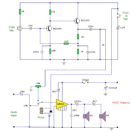
This is a circuit where a microphone and preamp circuit (voice circuit) have priority over any other audio signal. You can think of this as a one way intercom, if the main amplifier is used for listening to music, then when the push to talk switch is pressed, the amplifier is switched to the voice signal.
(View)
View full Circuit Diagram | Comments | Reading(1879)
Audio Signal Source
Published:2012/10/18 2:26:00 Author:muriel | Keyword: Audio, Signal Source

The circuit shown below can be roughly divided into three parts: the oscillator based around the ICL8038 chip, the selection logic based on the CD4017 and CD4066 and the offset generation and output buffers, based on the LF412. Apologies for the cramped schematic, I had to keep the image size small, and the width under 640 pixels!
The oscillator is a standard 8038-based oscillator circuit, taken from the ICL8038 datasheet. The timing resistor chosen is rather small, to give a wide range of frequencies. This range might be a little too large, making precise frequency setting difficult. In that case, the freqency range may be split into two parts, using two capacitors which can be switched using an SPDT switch. Note that the 8038 is powered from a split supply, not a single supply, to generate a symmetrical waveform without the need for capacitor coupling. Two sine wave adjustment terminals (Pins 1 and 12) are provided, however only one is used. This gives a sinewave distortion of about 1%. To achieve better distortion figures, the circuit shown in Figure 4 of the ICL8038 datasheet may be used. The 8038 is powered from slightly less than +8V to allow the tuning voltage to go above the supply rail. This allows for maximum sweep range (1000:1), however the output waveform tends to be slightly asymmetric because of this. This may be compensated using the offset control R10. R2 controls the duty cycle of the oscillator. R7 acts as the sinewave distortion adjustment. The square wave output of the 8038 is an open-collector output. Hence, a 1k pullup resistor is provided. The sine and triangle outputs are about 5Vpp, while the square wave is 16Vpp. Hence to equalize the different outputs, the square wave is attenuated using a fixed attenuator formed by R6 and R9. A 47k pot may be substituted to make the attenuation level adjustable. (View)
View full Circuit Diagram | Comments | Reading(2052)
Telephone Audio Interface
Published:2012/10/11 21:33:00 Author:muriel | Keyword: Telephone Audio, Interface
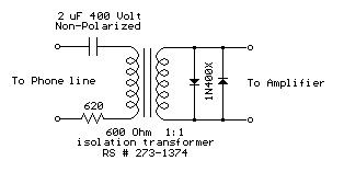
Audio from a telephone line can be obtained using a transformer and capacitor to isolate the line from external equipment. A non-polarized capacitor is placed in series with the transformer line connection to prevent DC current from flowing in the transformer winding which may prevent the line from returning to the on-hook state. The capacitor should have a voltage rating above the peak ring voltage of 90 volts plus the on-hook voltage of 48 volts, or 138 volts total. This was measured locally and may vary with location, a 400 volt or more rating is recommended. Audio level from the transformer is about 100 millivolts which can be connected to a high impedance amplifier or tape recorder input. The 3 transistor amplifier shown above can also be used. For overvoltage protection, two diodes are connected across the transformer secondary to limit the audio signal to 700 millivolts peak during the ringing signal. The diodes can be most any silicon type (1N400X / 1N4148 / 1N914 or other). The 620 ohm resistor serves to reduce loading of the line if the output is connected to a very low impedance.
(View)
View full Circuit Diagram | Comments | Reading(0)
Beeper 110dB
Published:2012/10/11 2:36:00 Author:muriel | Keyword: Beeper, 110dB
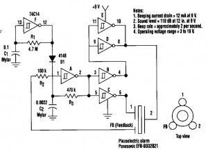
This beeper circuit will generate an car-splitting 110dB from 9V. The setup uses a single 74C14 (CD40106B) CMOS hex inverting Schmitt-trigger IC, which must be used with a piezoelectric device with a feedback terminal. The feedback terminal is attached to a central region on the piezoelectric wafer. When the beeper is driven at resonance, the feedback signal peaks.
One inverter of the 74C14 is wired as an astable oscillator. The frequency is chosen to be 5 times lower thant the 3,2KHz resonant frequency of the piezoelectric device. Feedback from the third pin of the beeper reinforces the correct drive frequency to ensure maximum sound output.
Four other inverter sections of the IC are wired to form two separate drivers. The output of one section is cross-wired to the input of the second section. The differential drive signal that results produces about 18Vpp when measured across the beeper. The last inverter section is wired as a second astable oscillator with a frequency of about 2 Hz. It gates the main oscillator on and off through a diode. For a continous tone, the modulation circuit can be deleted.
Beeper circuit diagram
(View)
View full Circuit Diagram | Comments | Reading(1224)
Musical doorbell circuit
Published:2012/10/11 2:33:00 Author:muriel | Keyword: Musical doorbell

In many cases, a doorbell that sounds off a musical tone is preferable over the common buzz sound. This featured circuit is a musical doorbell. After the button S1 is pressed, a short melody is played. When the button is pressed many times in rapid succession or pressed longer, a different melody is generated and the melody plays longer.The circuit works this way: when the button S1 is activated the inputs of U3 and one input of U1 switches to logic “0″. The data input (pin 7 of IC 4015) becomes logic “1″. The 4015 is a static 4-bit shift register. Each clock impulse coming from U4 shifts this logic “1″ further in the register. The clock frequency is around 5 Hz.
The number of shifted logic “1″ is directly dependent on the length of time the switch S1 is closed. Once at least one shift register is logic “1″, a current flows to the base of T1 through a corresponding resistor. The transistor T1 functions as a current controlled oscillator. The tone pitch is dependent on the logic state of the different flip-flop outputs of the shift register. Each clock pulse shifts the logic “1″ in the register. One output of the register (pin 2) is coupled back to U2 and U3 so that all the logic “1″ in the register always run in a loop.
Musical doorbell circuit diagram
When S1 is released (opened), the register runs until the capacitor C1 gets discharged through R2. When S1 is again pressed (closed), the capacitor C1 stays charged causing the musical bell to play continously.
The difference between two ways of activating the switch S1 is that different combinations of logic “1″ are inputted into the shift register. These different combinations produce the different melodies plyed by the circuit. The musical doorbell must be connected to an audio amplifier. The supply voltage is not critical. It can be between 5 and 15 volts. The circuit consumes around 15mA.
(View)
View full Circuit Diagram | Comments | Reading(1858)
Simple siren circuit
Published:2012/10/11 2:32:00 Author:muriel | Keyword: Simple siren circuit


This circuit generates a tone that sounds very similar to a siren. The generator part of the circuit is made of the combination of PNP and NPN transistors. Toghether, the two transistors build up a free runing multivibrator. If the C2 capacitor was connected to the positive line of the power supply, it would have worked as a constant frequency oscillator.However, we dont want a constant frequency oscillator. We want a siren. So to generate an up and down going signal tone, the resistor R2 is fed from an RC circuit. When the switch S1 is pressed, the capacitor C1 charges via R1 slowly until it reaches the maximum voltage level of 4 volts. This increasing voltage results to a decreasing time constant at the R2/C2 junction. This furthermore results to an increasing frequency of the multivibrator.
After the switch S1 is released, the capacitor C1 discharges slowly resulting to a decreasing frequency cycle. Through the combination of the two time constants a sawtooth waveform is generated.The signal heared from the speaker will be an increasing or decreasing tone depending on whether the switch S1 is pressed or released.
Siren circuit diagram
Siren PCB layout
(View)
View full Circuit Diagram | Comments | Reading(2046)
Touch controlled musical bell
Published:2012/10/11 2:23:00 Author:muriel | Keyword: Touch controlled, musical bell

This touch controlled musical bell circuit circuit produces a musical tone whenever someone touches the touch point designated as TP in the circuit. The circuit works from two AA cells and produces enough sound.The circuit uses IC UM 3481 commonly used in musical circuits. The IC contains a ROM with 512 musical notes, tone generator, rhythm generator, modulator, run off control, oscillators, frequency divider and preamplifiers,. So a very few number of components is required for this circuit.C1 and R1 act as the timing components for the built in oscillator. The transistor Q1 is used for driving the loud speaker. The base of the transistor Q2 is used as the touch point to trigger the musical bell.
Touch musical bell circuit diagram
(View)
View full Circuit Diagram | Comments | Reading(1885)
Electronic doorbell circuit
Published:2012/10/10 1:59:00 Author:muriel | Keyword: Electronic doorbell

This simple and cost-effective ding dong electronic doorbell circuit is based on IC 8021-2. The IC has an in-built circuitry to produce ding dong sound each time its pin 3 is pulled low. The sound is stored in the IC as bits, as in a ROM. The sound output from the IC can’t however drive a speaker directly, as this puts strain on the device.Therefore a complementary-pair, two-transistor amplifier is used to amplify the sound to a fair level of audiblity. You may either use a piezo tweeter or an 8-ohm, 500mW speaker at the output. This simple electronic doorbell has not been tested.
During the standby period, the IC consumes nominal current of a few microamperes only. Therefore switch S1 may be kept closed. Each time switch S2 is pressed, ding dong sound is produced twice. If you try to press switch S2 a second time when the first ding dong sound is still being produed, it has no effect whatever and the two ding-dong bell sounds will be invariably produced.
Doorbell electronic circuit diagram
(View)
View full Circuit Diagram | Comments | Reading(2023)
Audio Wattmeter circuit with LM3915
Published:2012/10/10 1:56:00 Author:muriel | Keyword: Audio Wattmeter circuit
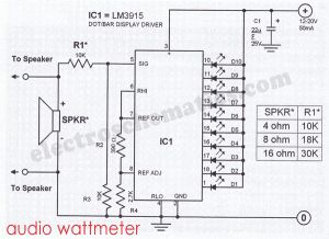

You need an audio wattmeter to measure the power output of your audio amplifier?You need one LM3915 IC and add a few passive components and you got a simple but effective audio wattmeter.This sound wattmeter uses a row of colored LEDs as a scale to show the relative power output of your amplifier in watts. It is easy to be inserted into the speaker box. All you need is to hook a supply voltage to it. The value of R1 depends upon the impedance of the speaker being used. The table near the sound wattmeter diagram shows the necessary values of R1.
LM3915 audio wattmeter circuit diagram
If you want to apply the circuit to stereo systems you must build two identical circuits.
The supply voltage of the circuit is 12…20 volts/50 mA DC adapter. Take note that the LM3915 indicates only the positive swing of the signal. Anyway, by testing amplifiers it does not matter anyhow since a sine wave is normally used as a test signal. To test the circuit without using an actual speaker, you can connect a dummy resistor with a value of either 8 or 4 ohms.
PCB layout and parts for the audio wattmeter
?
3 Responses to “Audio Wattmeter circuit with LM3915”
(View)
View full Circuit Diagram | Comments | Reading(3600)
Sawtooth Generator Circuit with 741 IC
Published:2012/10/10 1:54:00 Author:muriel | Keyword: Sawtooth Generator

This sawtooth generator circuit use 741 IC and is used as a musical sound synthesizer. The sawtooth input signal is continously changed through P2 to a waveform with a doubled frequency and half amplitude. IC1 functions as a comparator and forms the sawtooth to a squarewave signal. IC2 serves as a adder.The input signal and the converted signal are mixed to create the output signal. An additional LFO pulsewidth modulated the squarewave to give the output sound the desired effect. When switch S1 is switched to position B, the squarewave can be mixed with a freq. which is independent from the sawtooth.The current consumption is around 10 mA.
Sawtooth Generator Circuit Diagram
(View)
View full Circuit Diagram | Comments | Reading(2814)
Electronic Bicycle Horn circuit
Published:2012/10/8 2:46:00 Author:muriel | Keyword: Electronic Bicycle, Horn
This simple electronic bicycle horn circuit uses only one gate of a 4093 quad 2-input NAND Schmitt trigger, U1, conected in a simple, low frequency, square-wave oscillator circuit.The oscillator’s output, at pin 3, drives the gate of Q1. The drain of that FET drives a small horn speaker.
Potentiometer R1 can be adjusted to set the horn’s output frequency. Some horn speakers are frequency sensitive, so play with the oscillator’s frequency control for the best loudest sound.
Electronic Bike Horn Circuit Diagram
(View)
View full Circuit Diagram | Comments | Reading(1353)
Polyphonic DoorBell circuit
Published:2012/10/8 2:42:00 Author:muriel | Keyword: Polyphonic, DoorBell

Here is an AC triggered Multitone, polyphonic doorbell. It gives eight melodious tunes for 2 minutes. On each press it will give a new tone which will continue till the melody is over. The circuit is too simple and battery operated It uses the popular melody generator IC UM3481. The circuit uses the popular melody generator IC UM3481. It generates music tones like Jingle bell, Santa clause is coming, Silent night, Holy night, Joy to the world, Rudolph, Red nosed reindeer, Merry Christmas, O come, All Ye faithful, Hark and the herald angel sing.UM 3482 generates 12 music tones. Capacitor C1 and resistor R2 are the oscillation components. Pin1 can be triggered either by DC or AC. Here low voltage AC is applied to the trigger pin 1 through R1 and D1. The circuit works off two pen cells which last for more than one year
Caution: The circuit is connected to high volt AC. Do not touch any parts when it is powered to avoid lethal shock
Polyphonic DoorBell Circuit Diagram
UM 3481
AC187 Pinout
(View)
View full Circuit Diagram | Comments | Reading(1767)
MAX9730 2.4W Class G Power Amplifier
Published:2012/9/28 20:52:00 Author:muriel | Keyword: MAX9730, 2.4W, Class G, Power Amplifier

The MAX9730 features a mono Class G power amplifier with an integrated inverting charge-pump power supply. The charge pump can supply up to 500mA of peak output current over a 2.7VDC to 5.5VDC supply voltage range, guaranteeing up to 2.4W output power into an 8Ω load. The 2.4W output power allows for transient audio content to remain unclipped as the battery rail collapses over time. The MAX9730 maximizes battery life by offering high performance efficiency. Maxim’s proprietary output stage provides efficiency levels greater than Class AB devices without the EMI penalties commonly associated with Class D amplifiers. High efficiency allows the MAX9730 to be packaged in a WLP package without derating the output power handling capability.The device utilizes fully differential inputs and outputs, comprehensive click-and-pop suppression, shutdown control, and soft-start circuitry. The MAX9730 is fully specified over the -40°C to +85°C extended temperature range and is available in ultra-small, lead-free, 20-bump WLP (2mm x 2.5mm) and 28-pin TQFN (4mm x 4mm) packages.Download the MAX9730 datasheet…
MAX9730 Typical Application
(View)
View full Circuit Diagram | Comments | Reading(1469)
LA4440 Stereo Amplifier circuit
Published:2012/9/28 20:50:00 Author:muriel | Keyword: LA4440,Stereo Amplifier
LA4440 is a two channel audio power amplifier IC with inbuilt in dual channels enables it for stereo and bridge amplifier applications. In dual mode it gives 6 W per channel and in bridge mode 19 W output.
It has good ripple rejection of 46dB, small residual noise, built in over voltage and surge voltage protection etc. ideal feature of the IC is its pin-to-pin protection. Here LA4440 is wired in Stereo configuration using both inputs and outputs.
Features of LA4440
1. Built in two channels to use as Mono and Stereo2. Dual mode 6W x 2 and Bridge mode 19W3. 46 dB Ripple rejection4. 18V Max. Power handling and 12V typical5. Good channel separation and low distortion6. Built in Audio Muting function and Pin-to-Pin protection7. Surge protection circuitry
LA4440 Stereo Amplifier Circuit
(View)
View full Circuit Diagram | Comments | Reading(1678)
FM Stereo Noise Suppressor
Published:2012/9/27 21:34:00 Author:muriel | Keyword: FM, Stereo, Noise Suppressor

This fm stereo noise suppressor circuit is to be used when the reception of far FM stations is bad but improves when you switch the radio receiver to mono. The cause of this effect is that in stereo reception the biggest part of the noise in the right channel is in opposite phase with the noise in the left channel. Once the 2 channels are switched togheter (mono), the noise signals cancel each other and the result will be a clean and relatively noise free mono signal.
In order to use this effect in improving the signal but keeping the stereo character, the two channels should be switched together only in higher audio frequencies.
The stereo noise suppressor circuit is built in 2 identical channels each composed of 2 emitter-follower circuits. The switch S1 (single throw/3 poles switch) can connect the 2 channels together at 3 points. The circuit functions as a bridge between the left and right channel for opposing signal components above 8 kHz. These signals get “short-circuited” cancelling the noise. Otherwise, all other frequencies get through to the output via their respective channels.
If you want to lower the “short-circuit” freq. to 4 kHz, just double the values of C2, C3 and C4.T1 = T2 = 2SC734
FM Stereo Noise Suppressor circuit diagram
(View)
View full Circuit Diagram | Comments | Reading(1676)
Audio Noise Filter circuit
Published:2012/9/27 21:24:00 Author:muriel | Keyword: Audio, Noise Filter
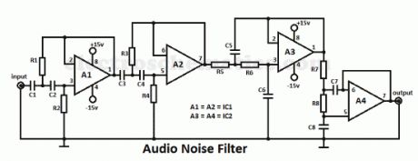
This audio noise filter circuit is a bandpass filter for audio frequency band. It filters unwanted signals that are lower or higher than the audio frequencies.It has 2 filters: a low pass filter and a high pass filter in a cascade configuration.Both filters are second-order filters with a 24 dB/octave fiter capability. The 3 dB cut-off freq. are 11.8 Hz and 10.7 kHz. The bandpass characteristic can be changed by changing the values of the capacitors and resistors. If you want to raise the bottom cut-off freq., you must reduce the values of C1 up to C4. For lowering the bottom cut-off freq. you must increase the values.
If you want to reduce the top cut-off f you must raise the values of R5 up to R8 and decrease it in order to increase the top cut-off frequency.
Noise Filter circuit diagram
Audio Noise Filter Parts ListR1 = R2 = 56kΩR3 = 39kΩR4 = 100kΩR5 = R6 = R7 = R8 = 3.3kΩC1 = C2 = C3 = C4 = 0.33µF ceramicC5 = C6 = 0.0033µF ceramicC7 = 0.0047µF ceramicC8 = 0.0018µF ceramicIC1 = IC2 = NE5532N (View)
View full Circuit Diagram | Comments | Reading(3852)
Electronic Siren Circuit
Published:2012/9/27 21:19:00 Author:muriel | Keyword: Electronic Siren
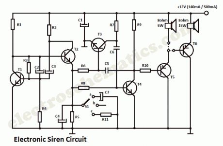
The DIY Electronic Siren circuit described here can create three different US-style siren sounds: DIY police, DIY ambulance and fire engine. The desired sound can be selected using switch S1. The circuit can be used in toys (such as model vehicles), as part of an alarm system, and in many other applications. For use in a toy, a BC337 is an adequate device for driver T5, since it is capable of directly driving a 200mW (8?) loudspeaker. In this case the current consumption from a 9 V power supply is around 140 mA. If a louder sound is required, a BD136 is recommended: this can drive a 5W (8?) loudspeaker. This will be the sound produced with the switch S1 on this positions:
a: Fire Brigade Siren
b: Police Siren
c: Ambulance Siren
The current consumption of the electronic siren from a 12 V supply will then be about 180mA. If still more volume is desired, then T5 (a BD136) can be used as a first driver stage, and a 15W (8?) loudspeaker can be connected via output transistor T6. Here an AD162 or an MJ2955 can be used, which, for continuous operation, must be provided with cooling. The peak current consumption of the circuit will now be about 500mA with a 12V power supply. Capacitor C1 is not required for battery operation.
Sent by Mihai Dorin, Romania. Thanks!
DIY Electronic Siren Circuit Diagram
Parts ListR1 = R9 = 2.2KΩR2 = 470ΩR3 = 47KΩR4 = R8 = 22KΩR5 = R6 = R7 = 18KΩR10 = 3.3KΩC1 = 100µF/16VC2 = 2.2µF/16VC3 = 10µF/16VC4 = 47µF/16VC5 = 22nFC6 = 33nFC7 = 470µF/16VT1 = T2 = T3 = T4 = BC547T5 = see textT6 = MJ2955, AD162
(View)
View full Circuit Diagram | Comments | Reading(2091)
Sound Generator: The Old West Sounds
Published:2012/9/26 21:21:00 Author:muriel | Keyword: Sound Generator
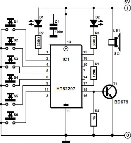
This sound generator circuit will produce 6 sound effects from the old west and it shows how far integration can be taken: IC1, a Type HT82207 from Holtek does virtually everything. Only a (small) loudspeaker and the necessary selectors need to be added.The standard 18-pin Type HT82207 is an integrated sound generator, producing sounds typical of the Old West. The various sounds are selected by S1 – S6 as listed below. In the quiescent state, the circuit draws a current not exceeding 1 μA. (View)
View full Circuit Diagram | Comments | Reading(1699)
| Pages:8/54 1234567891011121314151617181920Under 20 |
Circuit Categories
power supply circuit
Amplifier Circuit
Basic Circuit
LED and Light Circuit
Sensor Circuit
Signal Processing
Electrical Equipment Circuit
Control Circuit
Remote Control Circuit
A/D-D/A Converter Circuit
Audio Circuit
Measuring and Test Circuit
Communication Circuit
Computer-Related Circuit
555 Circuit
Automotive Circuit
Repairing Circuit