Audio Circuit
Index 12
Sixteen sound phonation circuit with CD4011,CD4066
Published:2011/7/22 2:55:00 Author:chopper | Keyword: Sixteen sound, phonation circuit

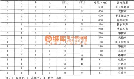
Sixteen sound phonation circuit adopts another analog phonation circuit KD9561.In accordance with internal fixed process of the circuit, there are 4 analog sound in the KD9561,such as machine gun sound, siren, ambulance soundand fire engine sound.It has two sound trigger ends SEL1 and SEL2, andthey can be triggered by high, low level or floatingthey respectively.
(View)
View full Circuit Diagram | Comments | Reading(4482)
15W Amplifier Circuit
Published:2011/8/11 5:55:00 Author:Sue | Keyword: Amplifier

The picture shows the 15W amplifier circuit. (View)
View full Circuit Diagram | Comments | Reading(1491)
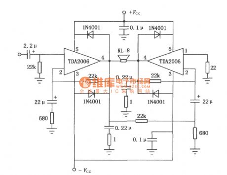
10W Audio power amplifier TDA2006 BTL application circuit diagram
Published:2011/8/22 22:15:00 Author:Rebekka | Keyword: 10W , Audio power amplifier, BTL application
View full Circuit Diagram | Comments | Reading(4318)
LM4811 Dual-channel headphone amplifier circuit diagram
Published:2011/8/22 22:16:00 Author:Rebekka | Keyword: Dual-channel , headphone amplifier
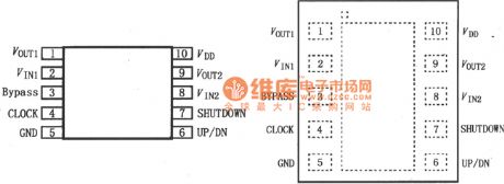
LM4811 is a dual channel headphone amplifier with 5V power supply. Each channel outputs 105mW continuous average power to drive 16Ω load. Total harmonic distortion plus noise (THD + N) is only 0.1%. LM4811 does not require bootstrap capacitor and buffer. It is qualified to low-power portable systems, cellular phones and the system MP3, CD, DVD players etc. LM4811 has an external control terminal. It has an effective high level shutdown mode to work in the micro-power. There is an internal thermal shutdown protection agency. LM4811 pinout is shown as the chart.
(View)
View full Circuit Diagram | Comments | Reading(1696)
STK4019 10W Audio power amplifier circuit diagram
Published:2011/8/15 2:17:00 Author:Rebekka | Keyword: 10W, Audio power amplifier

STK4019 10W Audio power amplifier circuit diagram is shown as below.
(View)
View full Circuit Diagram | Comments | Reading(1498)
TA7238P 9W Audio power amplifier circuit diagram
Published:2011/8/15 2:19:00 Author:Rebekka | Keyword: 9W, Audio power amplifier

TA7238P 9W Audio power amplifier circuit diagram is shown as below.
(View)
View full Circuit Diagram | Comments | Reading(1522)
TA7205P 5.8W Audio power amplifier circuit diagram
Published:2011/8/15 2:20:00 Author:Rebekka | Keyword: 5.8W, Audio power amplifier
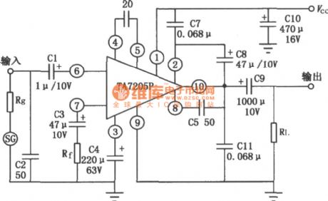
TA7205P 5.8W Audio power amplifier circuit diagram is shown as below.
(View)
View full Circuit Diagram | Comments | Reading(6377)
TBA820M 2W Audio power amplifier circuit diagram
Published:2011/8/15 2:36:00 Author:Rebekka | Keyword: Audio power amplifier

TBA820M 2W Audio power amplifier circuit diagram is shown as below.
(View)
View full Circuit Diagram | Comments | Reading(2608)
TCA830S 4.2W Audio power amplifier circuit diagram
Published:2011/8/15 2:35:00 Author:Rebekka | Keyword: 4.2W, Audio power amplifier
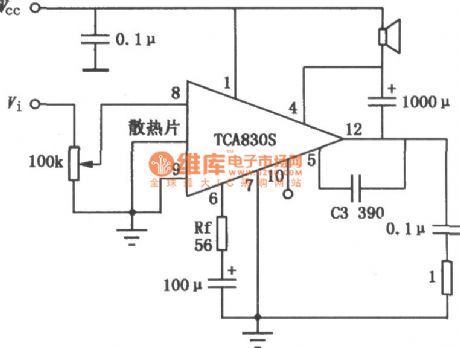
TCA830S 4.2W Audio power amplifier circuit diagram is shown as below.
(View)
View full Circuit Diagram | Comments | Reading(1525)
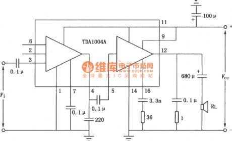
TDA1004A 10W Audio power amplifier circuit diagram
Published:2011/8/22 22:14:00 Author:Rebekka | Keyword: 10W , Audio power amplifier
View full Circuit Diagram | Comments | Reading(1687)
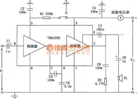
TDA1020 12W Audio power amplifier circuit diagram
Published:2011/8/22 22:14:00 Author:Rebekka | Keyword: 12W, Audio power amplifier
View full Circuit Diagram | Comments | Reading(1818)
M5112Y 5W Audio power amplifier circuit diagram
Published:2011/8/12 4:20:00 Author:Rebekka | Keyword: 5W, Audio power amplifier

M5112Y is 5W audio power amplifier integrated circuit. The circuit output power is large, less distortion, wide frequency bandwidth. It is suitable for car radio and stereo audio power amplifier device for stereo audio power amplifier. M5112Y 5W Audio power amplifier circuit diagram is shown as below.
(View)
View full Circuit Diagram | Comments | Reading(2756)
M51513L 5.8W Audio power amplifier circuit diagram
Published:2011/8/15 2:17:00 Author:Rebekka | Keyword: 5.8W, Audio power amplifier
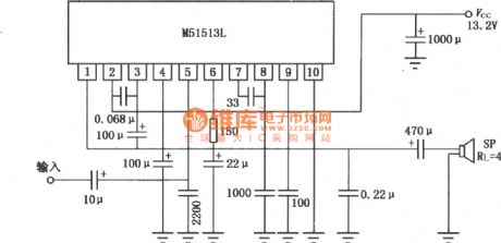
M51513L is theaudio power amplifier IC. It uses 10-pin single in-line plastic package. The features of the two ICs are high voltage gain, large output power and they even work in 2Ω load. The power supply voltage is 9~16V. The output power is 5.8W(Typical), when the power supply voltage is 13.2V, load impedance is 4Ω and distortion is 10%. There are short-circuit protection, thermal cut off, power surge voltage protection etc. in the circuit. It is suitable for the audio power amplifier of car radio, car stereo installation. The typical application circuit of M51513L is shown as below.
(View)
View full Circuit Diagram | Comments | Reading(3993)
AN7100S Two-track audio power amplifier circuit diagram
Published:2011/8/11 2:44:00 Author:Rebekka | Keyword: Two-track , audio power amplifier
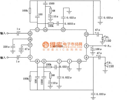
AN7100S is two-track audio power amplifier circuit diagram, which uses dual flat package. Its working power supply voltage is 1~3V. The circuit hasthe advantages of lowquiescent current, low noise and small distortion. It is suitable for 1.5V power supply voltage tape recorders. The max power supply voltage is VCC=3V. Power dissipation PD=60mW is available. The typical application circuit diagram is shown as below.
(View)
View full Circuit Diagram | Comments | Reading(2127)
AN7113S Audio power amplifier circuit diagram
Published:2011/8/11 2:21:00 Author:Rebekka | Keyword: audio power amplifier
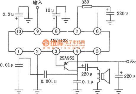
AN7113S is an audio power amplifier circuit with 10-pin dual flat package. The working power supply voltage is 1.8~4.5V. There isfew external components in the circuit. Its quiescent current can be adjusted by different loads. The circuit is suitable for low micro-radio or the power amplifier of tape recorders. The max power supply voltage of AN7113S is VCC=4.5V. Power dissipation PD=360mW(T=25℃) is available. AN7113S Audio power amplifier circuit diagram is shown as below.
(View)
View full Circuit Diagram | Comments | Reading(2616)
The typical application circuit diagram of AN102S dual track audio power amplifier
Published:2011/8/12 3:28:00 Author:Rebekka | Keyword: typical application , dual track , audio power amplifier
View full Circuit Diagram | Comments | Reading(906)
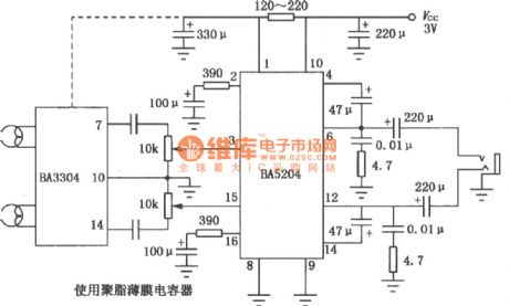
BA5204/5204F 3V Two-track audio power amplifier typical application circuit diagram
Published:2011/8/12 4:20:00 Author:Rebekka | Keyword: 3V, typical application , Two-tracll audio power amplifier
View full Circuit Diagram | Comments | Reading(1604)
CX20172 Two-track audio power amplifier circuit diagram
Published:2011/8/12 4:19:00 Author:Rebekka | Keyword: Two-track , audio power amplifier

CX20172 uses 14-pin dual flat package, operating supply voltage 0.9 ~ 2.2V. when Vcc is 1.5V, RL is 8Ω and THD is 10% the two-channel in the working mode. Every output channel power is 20mW. BTL connection output power is 80mW. There is not mute and power off function in circuit. The max power supply voltage is Vcc=4.5V and power dissipation PD=560mW(TA=25℃) is available. CX20172 Two-channel audio power amplifier circuit diagram is shown as below.
(View)
View full Circuit Diagram | Comments | Reading(1103)
HA1388 18W BTL Audio power amplifier circuit diagram
Published:2011/8/12 4:18:00 Author:Rebekka | Keyword: 18W BTL , Audio power amplifier
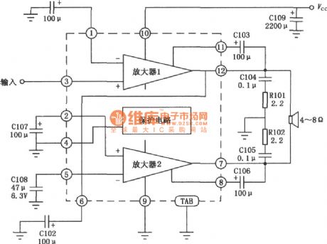
HA1388 is an audio power amplifier IC. It uses 12-pin single in-line plastic package structure. The output power is 18W without output coupling capacitor when the supply voltage is 13.2V, 4Ω load impedance and 10% distortion. Thereis overvoltage and thermal shutdown protection in the circuit and fewer external components. The audio Power Amplifier is suitable for car radio. HA1388 Internal circuit diagram and typical application circuit are shown as below.
(View)
View full Circuit Diagram | Comments | Reading(4026)
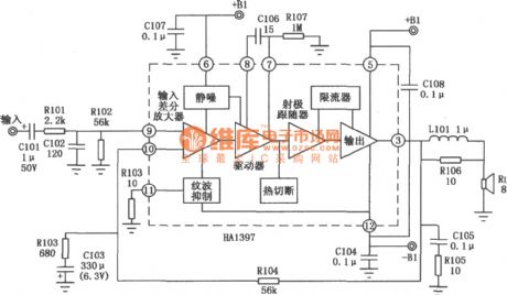
20W Audio power amplifier HA1397 typical application circuit diagram
Published:2011/8/12 4:18:00 Author:Rebekka | Keyword: typical application, Audio power amplifier
View full Circuit Diagram | Comments | Reading(3751)
| Pages:12/54 1234567891011121314151617181920Under 20 |
Circuit Categories
power supply circuit
Amplifier Circuit
Basic Circuit
LED and Light Circuit
Sensor Circuit
Signal Processing
Electrical Equipment Circuit
Control Circuit
Remote Control Circuit
A/D-D/A Converter Circuit
Audio Circuit
Measuring and Test Circuit
Communication Circuit
Computer-Related Circuit
555 Circuit
Automotive Circuit
Repairing Circuit
