Audio Circuit
Beeper 110dB
Published:2012/10/11 2:36:00 Author:muriel | Keyword: Beeper, 110dB | From:SeekIC

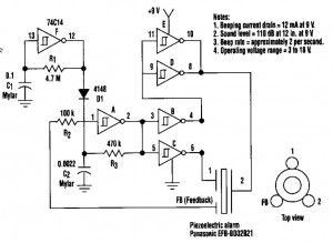
This beeper circuit will generate an car-splitting 110dB from 9V. The setup uses a single 74C14 (CD40106B) CMOS hex inverting Schmitt-trigger IC, which must be used with a piezoelectric device with a feedback terminal. The feedback terminal is attached to a central region on the piezoelectric wafer. When the beeper is driven at resonance, the feedback signal peaks.
One inverter of the 74C14 is wired as an astable oscillator. The frequency is chosen to be 5 times lower thant the 3,2KHz resonant frequency of the piezoelectric device. Feedback from the third pin of the beeper reinforces the correct drive frequency to ensure maximum sound output.
Four other inverter sections of the IC are wired to form two separate drivers. The output of one section is cross-wired to the input of the second section. The differential drive signal that results produces about 18Vpp when measured across the beeper. The last inverter section is wired as a second astable oscillator with a frequency of about 2 Hz. It gates the main oscillator on and off through a diode. For a continous tone, the modulation circuit can be deleted.
Beeper circuit diagram
Reprinted Url Of This Article:
http://www.seekic.com/circuit_diagram/Audio_Circuit/Beeper_110dB.html
Print this Page | Comments | Reading(3)

Article Categories
power supply circuit
Amplifier Circuit
Basic Circuit
LED and Light Circuit
Sensor Circuit
Signal Processing
Electrical Equipment Circuit
Control Circuit
Remote Control Circuit
A/D-D/A Converter Circuit
Audio Circuit
Measuring and Test Circuit
Communication Circuit
Computer-Related Circuit
555 Circuit
Automotive Circuit
Repairing Circuit
Code: