
Index 133
800_watt_triac_light_dimmer
Published:2009/7/21 7:25:00 Author:Jessie

800-watt triac light dimmer (courtesy Motorola Semiconductor Products Inc.). (View)
View full Circuit Diagram | Comments | Reading(697)
AC_controlled_triac_switch_R1_is_100_ohms
Published:2009/7/21 7:31:00 Author:Jessie
AC-controlled triac switch. R1 is 100 ohms (courtesy Motorola Semiconductor Products Inc.). (View)
View full Circuit Diagram | Comments | Reading(605)
Three_position_static_switch
Published:2009/7/21 7:31:00 Author:Jessie

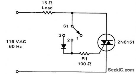

Three-position static switch. In position 1 the switch is off ; in position 2 the switch supplies full-wave power to the load; in position 3 the diode conducts only on half-cycles and the load is supplied with half-wave power (courtesy Motorola Semiconductor Products Inc.). (View)
View full Circuit Diagram | Comments | Reading(863)
Triac_AC_static_contactor
Published:2009/7/21 7:29:00 Author:Jessie

Triac AC static contactor (courtesy Motorola Semiconductor Products Inc.). (View)
View full Circuit Diagram | Comments | Reading(643)
12_VDC_TO_117_VAC_AT_60_Hz_POWER_INVERTER
Published:2009/7/7 9:32:00 Author:May

Capacitor C5 and potentiometer R12 determine the frequency of the output signal at pin 3 of IC1, the 555 oscillator. The output signal is differentiated by C3 and C4 before it's input to the base of power tran-sistors Q1 and Q2 via diodes Dl and D2, respectively. The signal from IC1 is adjusted to 120 Hz, because the f[ip-flop formed by transistors Q3 and Q4 divides the frequency by 2.When Q3 is on, the base of Q1 is connected via RI to the regulated 12-V supply. Then, when the flip-flop changes states, Q4 is turned on and the base of Q2 connected to the 12-V supply through R2. The 100 mA base current allows Q1 and Q2 to alternately conduct through their respective halves to the transform-er's secondary winding.To eliminate switching transients caused by the rapid switching of Q3 and Q4, capacitors C1 and C2 filter the inputs to the base of Q1 and Q2 respectively. Power for the unit comes from an automobile's 12-V system or from a storage battery. The power is regulated by IC2, a 7812 regulator. LED1, connected across the 12-V input, can be used to indicate whether power is being fed to the circuit. The neon pilot lamp, LMP1, shows a presence or absence of output power. (View)
View full Circuit Diagram | Comments | Reading(801)
Low_voltage_controlled_triac_switch
Published:2009/7/21 7:50:00 Author:Jessie

Low-voltage-controlled triac switch (courtesy Motorola Semiconductor Products Inc.). (View)
View full Circuit Diagram | Comments | Reading(779)
Simple_full_wave_power_control_circuit_using_a_triac
Published:2009/7/21 7:48:00 Author:Jessie

Simple full-wave power control circuit using a triac (courtesy Motorola Semiconductor Products Inc.). (View)
View full Circuit Diagram | Comments | Reading(819)
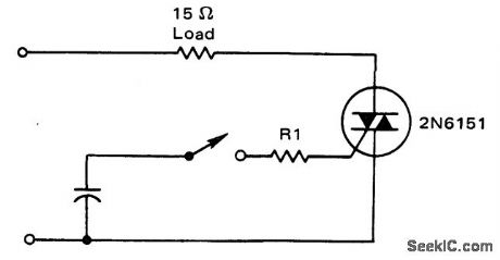
Simple_DC_power_control_circuit_using_an_SCR
Published:2009/7/21 7:47:00 Author:Jessie

Simple DC power control circuit using an SCR (courtesy Motorola Semiconductor Products Inc.). (View)
View full Circuit Diagram | Comments | Reading(1141)
Full_wave_average_voltage_feedback_control_circuit_for_a_600_watt_load
Published:2009/7/21 7:46:00 Author:Jessie
Full-wave average voltage feedback control circuit for a 600-watt load (courtesy Motorola Semiconductor Products Inc.). (View)
View full Circuit Diagram | Comments | Reading(656)
240_volt_triac_control_circuit_driven_by_two_MOC3011_optically_coupled_tdac_drivers
Published:2009/7/21 7:59:00 Author:Jessie

240-volt triac control circuit driven by two MOC3011 optically coupled tdac drivers (courtesy Motorola Semiconductor Products Inc.).
(View)
View full Circuit Diagram | Comments | Reading(1049)
RMS_open_loop_voltage_compensator_regulator_for_small_conduction_angles
Published:2009/7/21 7:57:00 Author:Jessie
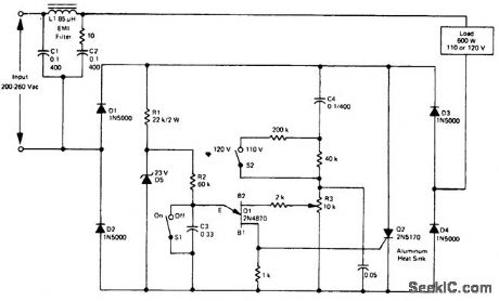
RMSopen-loop voltage compensator (regulator) for small conduction angles. This circuit provides an output of 110/115 ±2.5 volts at 600 watts for an input of 200 to 260 volts. This circuit is suitable for applications requiring a conduction angle of less than 90 (courtesy Motorola Semiconductor Products Inc.). (View)
View full Circuit Diagram | Comments | Reading(531)
Proportional_controller_for_heater_using_two_op_amps
Published:2009/7/21 7:56:00 Author:Jessie
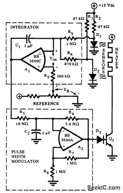
Proportional controller for heater using two op amps. The integrating error amplifier holds the heater current pulse width at a sustaining value at equilibrium (courtesy Burr-Brown Research Corporation). (View)
View full Circuit Diagram | Comments | Reading(717)
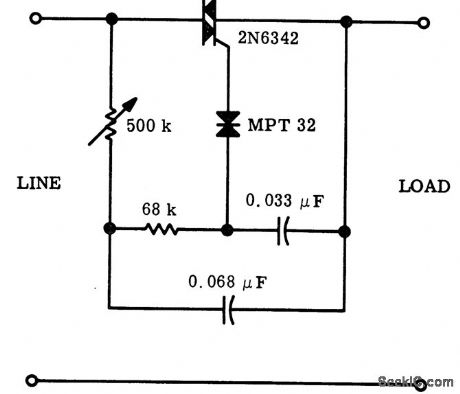
Full_wave_variable_AC_control_for_motors_and_lamps_using_a_triac_and_triac
Published:2009/7/21 7:52:00 Author:Jessie
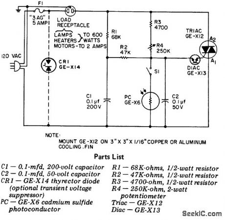
Full-wave variable AC control for motors and lamps using a triac and triac. This circuit gives full symmetrical control from 0 to 100% over the AC load. For fan or blower operation it may be desirable to place a 100-ohm 1 -watt resistor in series with a 0.1μF capacitor directly across the triac to improve performance. Best operation is achieved when the circuit is adjusted during the brightest part of the day. R4 is adjusted so that the lamp plugged into the outlet is lust off. In this manner as it gets darker the light will come on (courtesy General Electric Company). (View)
View full Circuit Diagram | Comments | Reading(1484)
D_C_TRIGGER_DRIVES_HIGH_C_COAX
Published:2009/7/21 8:03:00 Author:Jessie

Emitter-follower incorporated in Schmitt circuit provides signal shaping needed to drive high-capacitonce cable with good rise time and few components.-G. Klein, Schmitt Trigger Drives Low Impedance Loads, Electronics, 36:33, p 28-29. (View)
View full Circuit Diagram | Comments | Reading(786)
M6800_microprocessor_to_115_volt_AC_load_interface_using_optically_coupled_MOC3011_triac_drivers
Published:2009/7/21 8:08:00 Author:Jessie
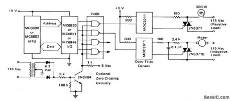
M6800 microprocessor to 115-volt AC load interface using optically coupled MOC3011 triac drivers (courtesy Motorola Semiconductor Products Inc.). (View)
View full Circuit Diagram | Comments | Reading(1705)
SECOND_AUDIO_PROGRAM_ADAPTER
Published:2009/7/7 8:02:00 Author:May
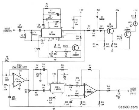
The baseband-audio input comes from the pole of switch S1 in the stereo decoder, and is coupled to IC1 (a CA3089) via a 78.6 kHz bandpass filter that consists of capacitors C1 and C2, and inductor L1. IC1 is a combination i-f amplifier and quadrature detector normally used for FM radio systems operating within an i-f of 10.7 MHz. The device works equally well at 78.6 kHz. Capacitors C6 and C7, and inductor L2 tune the detector section to 78.6 kHz, while C5 provides the necessary 90-degree phase shift for proper quadrature detector operation. The output voltage at pin 13 of IC1 is proportional to the level of the incom-ing signal. When the voltage at the wiper of potentiometer R3 reaches a predetermined threshold level, Q1 conducts, grounding pin 5 of IC1, enabling 101's mute function.
Detected audio output from pin 6 of IC1 goes to IC2a, which is configured as a 12-kHz, -12 dB per octave, low-pass filter. The output of IC2a appears across potentiometer R10, which provides a means of adjusting the drive level into IC3b, the 2:1 compander.
Audio from the wiper of R10 is split into two paths: a high-pass filter (C14 and R8) provides a path to the rectifier input of the compander, and a bandpass filter (R9, C16, and C15) that feeds the audio input of the compander. A fixed 390-μs de-emphasis network is formed by C18 and R11 in conjunction with IC3b, Corrected audio appears at pin 10 of IC3b and is coupled to IC2b, and output buffer amplifier.
Audio from pin 6 of IC1 is also coupled to an audio high-pass filter, R5 and C10, and fed to an audio rectifier, D1, D2, and C11. When a SAP signal is detected by IC1, it is rectified by D1 and D2; the resultant dc charges C11. An increasing positive voltage at the base of Q2 causes its current flow to decrease, so the voltage at Q2's collector also decreases. That in turn causes the base voltage of Q3 to drop, which causes Q3 to conduct, thereby lighting the LED. (View)
View full Circuit Diagram | Comments | Reading(2786)
Full_range_AC_power_control_circuit_using_a_triac
Published:2009/7/21 8:05:00 Author:Jessie
Full range AC power control circuit using a triac (courtesy Motorola Semiconductor Products Inc.). (View)
View full Circuit Diagram | Comments | Reading(1800)
Direction_and_speed_control_for_shunt_wound_motors
Published:2009/7/21 8:04:00 Author:Jessie
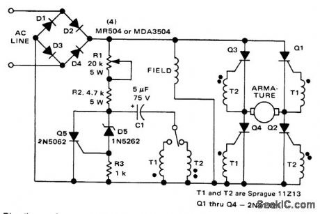
Direction and speed control for shunt-wound motors (courtesy Motorola Semiconductor Products Inc.). (View)
View full Circuit Diagram | Comments | Reading(1822)
Half_wave_average_voltage_control_circuit_for_a_600_watt_load
Published:2009/7/21 8:11:00 Author:Jessie

Half-wave average voltage control circuit for a 600-watt load (courtesy Motorola Semiconductor Products Inc.). (View)
View full Circuit Diagram | Comments | Reading(565)
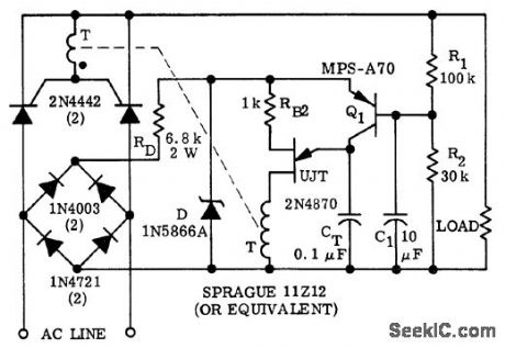
Full_wave_trigger_circuit_for_a_900_watt_load_using_a_triac_and_UJT
Published:2009/7/21 8:10:00 Author:Jessie

Full-wave trigger circuit for a 900-watt load using a triac and UJT (courtesy Motorola Semiconductor Products Inc.). (View)
View full Circuit Diagram | Comments | Reading(1222)
| Pages:133/291 At 20121122123124125126127128129130131132133134135136137138139140Under 20 |
Circuit Categories
power supply circuit
Amplifier Circuit
Basic Circuit
LED and Light Circuit
Sensor Circuit
Signal Processing
Electrical Equipment Circuit
Control Circuit
Remote Control Circuit
A/D-D/A Converter Circuit
Audio Circuit
Measuring and Test Circuit
Communication Circuit
Computer-Related Circuit
555 Circuit
Automotive Circuit
Repairing Circuit