
Index 452
Composed of LM2641 5V/3A, 3.3V/4A, 12V/0.3A and 5V/0.025A four outputs power supply circui diagram
Published:2011/4/1 3:18:00 Author:Rebekka | Keyword: four output , power supply

Composed of LM2641 5V/3A, 3.3V/4A, 12V/0.3A and 5V/0.025A four outputs power supply circui diagram. LM2641 is a dual adjustable step-down switch power supply controller. Output voltage 5.5~30V, 2.2~8V, dual output adjustable, working rate 300kHz, load regulation error 0.5%. Soft start available, with undervoltage and overvoltage protection.
(View)
View full Circuit Diagram | Comments | Reading(1131)
Composed of 4 codes synchronous step-down controller CS5150H 12V bias voltage 3.3V to 2.5V/7.0A converter circuit diagram
Published:2011/4/1 3:10:00 Author:Rebekka | Keyword: step-down controller , Composed of CS5150H, 3.3V to 2.5V/7.0A converter

Composed of 4 codes synchronous step-down controller CS5150H 12V bias voltage 3.3V to 2.5V/7.0A converter circuit diagram is shown as below.
4-bit DAC codes feature:
(View)
View full Circuit Diagram | Comments | Reading(596)
Composed of 4 codes synchronous step-down controller CS5150H 5.0V to 3.3V/10A converter circuit diagram
Published:2011/4/1 3:07:00 Author:Rebekka | Keyword: step-down controller , 5.0V to 3.3V/10A converter

Composed of 4 codes synchronous step-down controller CS5150H 5.0V to 3.3V/10A converter circuit diagram is shown as below.
(View)
View full Circuit Diagram | Comments | Reading(624)
4 Codes Synchronous step-down controller composed of CS5150H current sharing 5.0V to 3.3V/10A converter circuit diagram
Published:2011/3/31 4:39:00 Author:Rebekka | Keyword: 4 Codes Synchronous, step-down controller current sharing

4 Codes Synchronous step-down controller composed of CS5150H current sharing 5.0V to 3.3V/10A converter circuit diagram is shown as below.
(View)
View full Circuit Diagram | Comments | Reading(576)
4 Codes synchronous step-down controller composed of CS5150H 5.0V to 3.3V/10A converter circuit diagram
Published:2011/3/31 4:44:00 Author:Rebekka | Keyword: Synchronous step-down controller, synchronous step-down controller

4 Codes Synchronous step-down controller composed ofCS5150H 5.0V to 3.3V/10A converter circuit diagram is shown as below.
(View)
View full Circuit Diagram | Comments | Reading(491)
Composed of CS5157H current sharing 5.0V to 3.3V/10A converter circuit diagram
Published:2011/3/31 4:44:00 Author:Rebekka | Keyword: current sharing , 5.0V to 3.3V/10A converter

Composed of CS5157H current sharing 5.0V to 3.3V/10A converter circuit diagram is shown as below.
(View)
View full Circuit Diagram | Comments | Reading(571)
Composed of CS5157H l2V to 3.3V/5.0A remote testing converter circuit diagram
Published:2011/4/1 3:03:00 Author:Rebekka | Keyword: l2V to 3.3V/5.0A converter, remote testing

Composed of CS5157H l2V to 3.3V/5.0A remote testing converter circuit diagram is shown as below.
(View)
View full Circuit Diagram | Comments | Reading(514)
Composed of CS5157H 12V bias voltage 3.3V to 2.5V/7A converter circuit diagram
Published:2011/4/1 3:01:00 Author:Rebekka | Keyword: 12V bias voltage , 3.3V to 2.5V/7A converter

Composed of CS5157H 12V bias voltage 3.3V to 2.5V/7A converter circuit diagram is shown as below.
(View)
View full Circuit Diagram | Comments | Reading(934)
Composed of CS5157H 5.OV to 3.3V/10A converter circuit diagram
Published:2011/4/1 3:00:00 Author:Rebekka | Keyword: 5.OV to 3.3V/10A converter

Composed of CS5157H 5.OV to 3.3V/10A converter circuit diagram is shown as below.
(View)
View full Circuit Diagram | Comments | Reading(572)
Front and rear control assmebly、rear model actuator and twin-stage nozzle relay circuit diagram
Published:2011/4/10 22:46:00 Author:muriel | Keyword: Front and rear control assmebly, rear model actuator , twin-stage nozzle relay
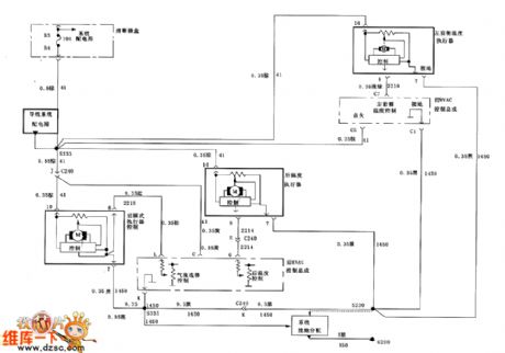
Figure Front and rear control assmebly、rear model actuator and twin-stage nozzle relay circuit diagram (View)
View full Circuit Diagram | Comments | Reading(621)
Voltage-division bias amplifier circuit of transistor circuit
Published:2011/3/31 4:17:00 Author:Joan | Keyword: Voltage-division bias amplifier
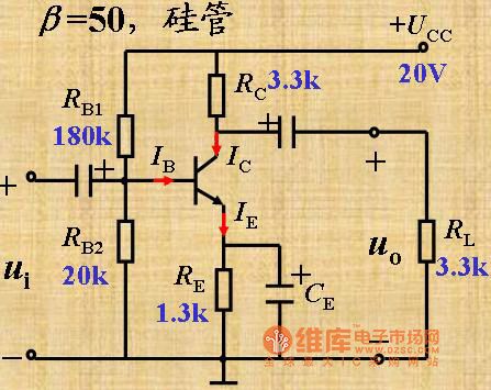
Below is Transistor used as voltage-division, bias device and amplifier circuit.
(View)
View full Circuit Diagram | Comments | Reading(1127)
1500V isolating circuit of D/A convertor
Published:2011/4/2 3:00:00 Author:may | Keyword: 1500V, isolating, D/A convertor
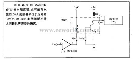
This circuit uses Motorala 4N27 optoelectronic isolator. It offers needed isolate between D/A convertor of programmable power supply and CMOS MC1408 noninvert buffer on the beyond.
(View)
View full Circuit Diagram | Comments | Reading(434)
DMAl2 function diagram
Published:2011/4/10 20:13:00 Author:may | Keyword: function
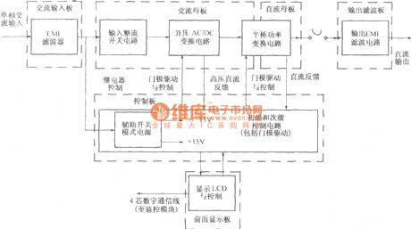

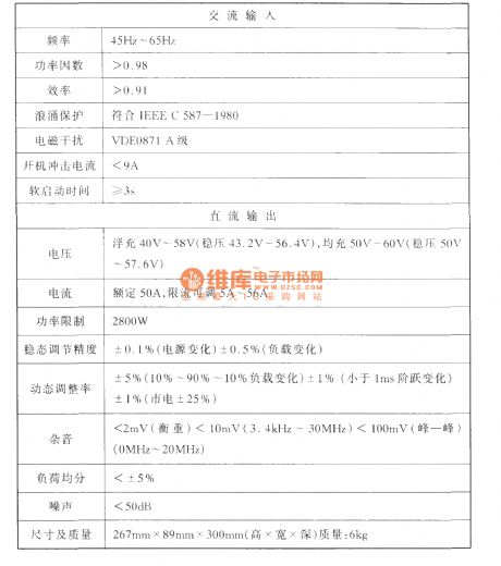
Compare to DMA10 type rectification module, the selection of working frequency and the topological structure of power inversion of DMA12 type rectification module is the same. The difference is, DMA12 using the compensation mode of single phase active boost power factor and natural cooling, and using the technique of non loss absorption. The diagram is its function diagram. The capacity of DMA12 type rectification module’s 48V power-supply system is 50A. The canonical system now is DUM23 series integrated power supply system. The technical target of 48V/50A rectification module is shown in the following table:
(View)
View full Circuit Diagram | Comments | Reading(436)
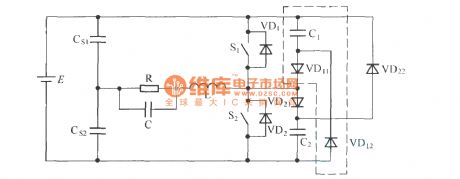
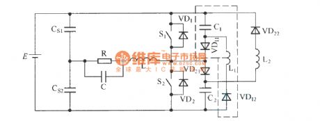
The circuit of C-2D type passive non loss buffer circuit application in DC/AC half bridge converter
Published:2011/4/10 21:43:00 Author:may | Keyword: passive, non , loss buffer, DC/AC half bridge converter
View full Circuit Diagram | Comments | Reading(393)
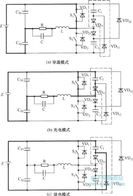
The working model of C-2D type passive non loss buffer circuit
Published:2011/4/10 21:39:00 Author:may | Keyword: working model, passive, non loss, buffer
View full Circuit Diagram | Comments | Reading(494)
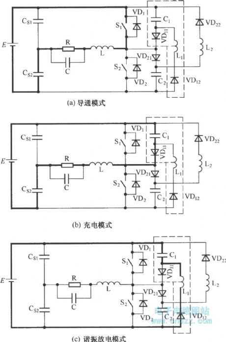
The working model of C-L-2D type passive non loss buffer circuit
Published:2011/4/10 21:38:00 Author:may | Keyword: working model, passive, non loss, buffer
View full Circuit Diagram | Comments | Reading(397)
C-L-2D type passive non loss buffer circuit
Published:2011/4/10 21:37:00 Author:may | Keyword: passive, non loss, buffer
View full Circuit Diagram | Comments | Reading(401)
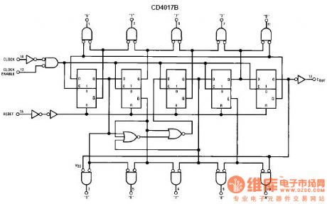
cd4017 principle and application Circuit
Published:2011/4/7 21:56:00 Author:Ecco | Keyword: principle , application
View full Circuit Diagram | Comments | Reading(1291)
The braking circuit diagram with relaxed brake after outage
Published:2011/4/5 22:22:00 Author:Ecco | Keyword: braking circuit , relaxed brake , outage
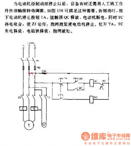
When the motor is stopped by the brake, the device will sometimes need to use manual to do the job of shaft rotation adjustment. Figure 116 can meet this need. When braking, to press the stop button TA of the motor , QC contactor releases, motor interrupts. At the same time, TC gets electric and pulls in, so that ZJ acts, the brake holds to stop the motor. To relax TA, TC losses power and releases, brake relaxes. (View)
View full Circuit Diagram | Comments | Reading(396)
RF probe with negative pressure source circuit diagram
Published:2011/4/7 21:51:00 Author:Ecco | Keyword: RF probe , negative pressure source

View full Circuit Diagram | Comments | Reading(501)
| Pages:452/471 At 20441442443444445446447448449450451452453454455456457458459460Under 20 |
Circuit Categories
power supply circuit
Amplifier Circuit
Basic Circuit
LED and Light Circuit
Sensor Circuit
Signal Processing
Electrical Equipment Circuit
Control Circuit
Remote Control Circuit
A/D-D/A Converter Circuit
Audio Circuit
Measuring and Test Circuit
Communication Circuit
Computer-Related Circuit
555 Circuit
Automotive Circuit
Repairing Circuit