
Index 450
Low cost CFL electronic ballast circuit with IGBT switch
Published:2011/3/23 21:27:00 Author:muriel | Keyword: Low cost , CFL electronic ballast circuit, IGBT switch, MUR180

View full Circuit Diagram | Comments | Reading(3234)
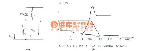
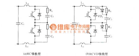
IGBT turn-off voltage waveform in the hard switching chopper circuit
Published:2011/3/23 21:29:00 Author:muriel | Keyword: IGBT , turn-off voltage waveform, hard switching , chopper circuit
View full Circuit Diagram | Comments | Reading(1376)
Bypass switch with IGBT
Published:2011/3/23 21:37:00 Author:muriel | Keyword: Bypass switch, IGBT

View full Circuit Diagram | Comments | Reading(577)
QRC Soft Switching flyback converter schematic diagram
Published:2011/3/23 21:44:00 Author:muriel | Keyword: QRC , Soft Switching, flyback converter , schematic diagram
View full Circuit Diagram | Comments | Reading(1078)
IF HVPS PWM circuit
Published:2011/3/23 21:48:00 Author:muriel | Keyword: IF, HVPS , PWM circuit, SG3524, PM10CSJ060
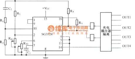
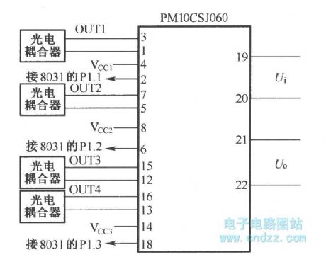
The connection of PWM signal and IPM intelligent power module PM10CSJ060 :
(View)
View full Circuit Diagram | Comments | Reading(813)
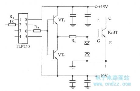
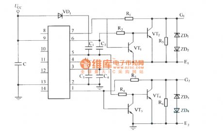
Driver with integrated circuit TLP250
Published:2011/3/23 21:49:00 Author:muriel | Keyword: Driver , integrated circuit, TLP250
View full Circuit Diagram | Comments | Reading(8889)
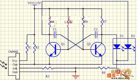
Light control LED flashing circuit diagram
Published:2011/4/12 22:44:00 Author:Rebekka | Keyword: Light control LED flashing
View full Circuit Diagram | Comments | Reading(530)
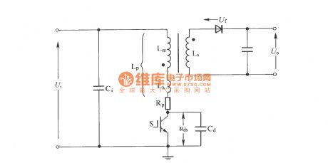
Regenerative passive lossless buffer circuit
Published:2011/3/24 1:09:00 Author:muriel | Keyword: Regenerative, passive, lossless, buffer circuit
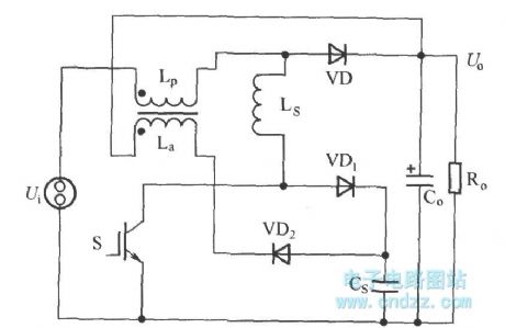
As shown in figure is a passive regenerative soft switch Boost converter, it is the traditional L + RCVD complex buffer circuit's improvement. Its improved place include: Remove the discharge resistance R with input power inductor Lp coupled miniwatt winding La instead of special power inductor L. (View)
View full Circuit Diagram | Comments | Reading(953)
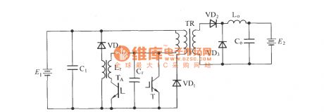
Forward ZVT-PWM converter main circuit schematic diagram
Published:2011/3/24 1:11:00 Author:muriel | Keyword: Forward ZVT-PWM converter , main circuit, schematic diagram
View full Circuit Diagram | Comments | Reading(429)
Forward Converter circuit
Published:2011/3/24 1:12:00 Author:muriel | Keyword: Forward Converter circuit

View full Circuit Diagram | Comments | Reading(521)
Sine wave intermediate frequency inverter main circuit
Published:2011/3/24 1:14:00 Author:muriel | Keyword: Sine wave , intermediate frequency , inverter main circuit
View full Circuit Diagram | Comments | Reading(906)
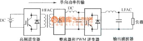
Unidirectional voltage source HFDL inverter block diagram
Published:2011/3/24 1:16:00 Author:muriel | Keyword: Unidirectional voltage source, HFDL , inverter block diagram
View full Circuit Diagram | Comments | Reading(520)
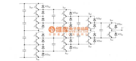
Capacitor voltage self-balance 5 level Single-phase translation circuit
Published:2011/3/24 1:35:00 Author:muriel | Keyword: Capacitor voltage , self-balance, 5 level , Single-phase, translation circuit
View full Circuit Diagram | Comments | Reading(811)
Voltage sourece three phase inverter structure chart
Published:2011/3/24 1:38:00 Author:muriel | Keyword: Voltage sourece, three phase, inverter structure chart

View full Circuit Diagram | Comments | Reading(1855)
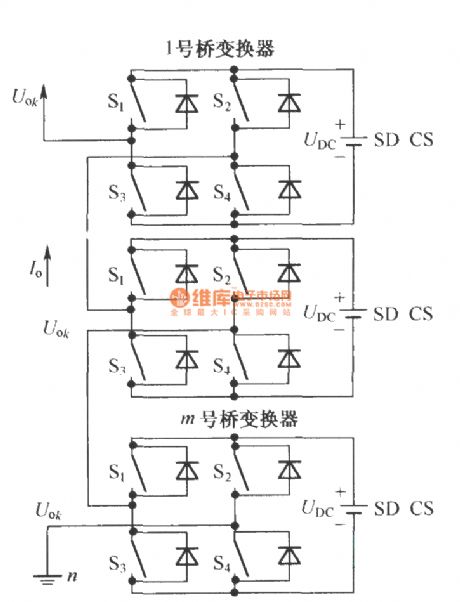
Cascade H-Bridge multilevel main circuit converter
Published:2011/3/24 1:42:00 Author:muriel | Keyword: Cascade H-Bridge, multilevel, main circuit, converter
View full Circuit Diagram | Comments | Reading(916)
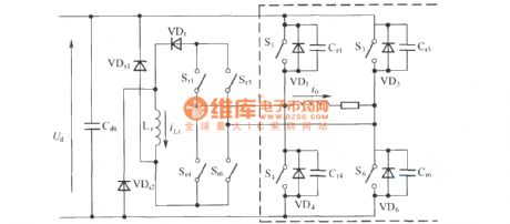
Charge discharge IGBT turn-off buffer absorbing circuit
Published:2011/3/24 1:43:00 Author:muriel | Keyword: Charge discharge, IGBT, turn-off , buffer, absorbing circuit
View full Circuit Diagram | Comments | Reading(534)
IR2110 drive circuit with level clamp function
Published:2011/3/24 1:45:00 Author:muriel | Keyword: IR2110, drive circuit, level clamp function
View full Circuit Diagram | Comments | Reading(3184)
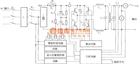
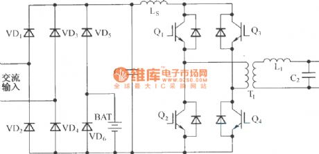
Double transform type UPS with output transformer
Published:2011/3/24 20:48:00 Author:muriel | Keyword: Double transform type, UPS, output transformer
View full Circuit Diagram | Comments | Reading(548)
single phase full-bridge equivalent circuit
Published:2011/3/24 20:51:00 Author:muriel | Keyword: single phase , full-bridge , equivalent circuit
View full Circuit Diagram | Comments | Reading(411)
Electric appliances socket connecting to zero circuit diagram
Published:2011/4/12 22:06:00 Author:Ecco | Keyword: Electric appliances socket , connecting to zero
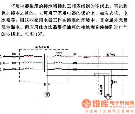
To connect the earth terminal of electric appliances socket to zero line in three-phase four-wire system, it can reach the purpose of protecting access to zero. It can be used on the protection of home appliances such as washing machines, refrigerators and so on. As these electric appliances work in wet environment, it needs to connect the earth terminal of electric appliances socket to zero line before entering family. Look figure 137. (View)
View full Circuit Diagram | Comments | Reading(469)
| Pages:450/471 At 20441442443444445446447448449450451452453454455456457458459460Under 20 |
Circuit Categories
power supply circuit
Amplifier Circuit
Basic Circuit
LED and Light Circuit
Sensor Circuit
Signal Processing
Electrical Equipment Circuit
Control Circuit
Remote Control Circuit
A/D-D/A Converter Circuit
Audio Circuit
Measuring and Test Circuit
Communication Circuit
Computer-Related Circuit
555 Circuit
Automotive Circuit
Repairing Circuit